-
-
GU-U100 Series
Graphic VFD (Vacuum Fluorescent Display) Modules
Replacing from 128×64 Graphic LCD
GU128X64E-U100 supports KS0108 commands and has the same footprint making transition from LCD graphic display an ease.
Product
GU128X64E-U100
Supports KS0108 commands
Has the same footprint of typical 128×64 LCD graphic modules
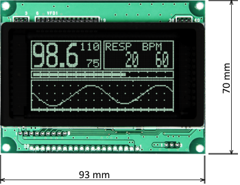
Specifications
Part Number Character Number Resolution Display Area (mm) Dot Pitch (mm) PCB Size (mm) Operating Temp Storage Temp Weight (g) Power Interface LCD Controller Font Table Specification
DatasheetCAD
DataNOTE
1. "N/A" means "Not Available".
2. The specification table above are summarised information, so please confirm further details on the respective detail specification.
Benefits of GU-U100 vs LCD
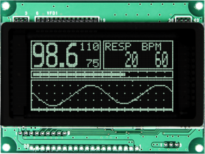
Display for Best Readability
GU128X60E-U100 is inteded for applications with 128×64 LCD graphic display that have poor readability and/or rapidly changing content. GU128X60E-U100, being emissive display is viewable from wide angles solving readability problem. The response time and refresh rate is also faster than 128×64 LCD graphic displays, eliminating ghost images from the display.
Buy evaluation sample >
What makes GU128X64E-U100, 128×64 VFD graphic display for best readability?
- Easy to read high contrast display.
- High brightness. Unlike the LCD graphic display, only the dots that are ON are brighter, not the entire display.
- Color filter can alter the illumination color and increase the contrast of the display.
- Wide viewing angle display. The display content WILL NOT wash-out like the LCD graphic display.
- Faster display response time and refresh rate allowing data to display clearly.

Reduce the development time
Replacing from 128×64 Graphic LCD
GU128X64E-U100 supports KS0108 commands and has the same footprint making transition from LCD graphic display an ease.
For New design
GU128X64E-U100 is simpler to connect requiring a single 5V power supply, no contrast adjustment, and 3 types of serial interfaces requiring fewer pins. Serial and parallel interfaces are included in the code library with manufacturer recommended timings.
Download the code library >
Long term support
Noritake has supported global demands for industrial displays since 1966. Because of their high quality and life cycles in excess of 10 years, Noritake has enjoyed a long-standing reputation with Fortune 100 companies.
Long term support
Noritake has supported global demands for industrial displays since 1966. Because of their high quality and life cycles in excess of 10 years, Noritake has enjoyed a long-standing reputation with Fortune 100 companies.
We offer the assistance of experienced and qualified application engineers nationwide, working hand-in-hand to solve customer’s problems and ensure reliable display solutions.
Just-in-time (JIT) programs are also available.
Factory ISO9001 and ISO14001 Certified
Withstand the most demanding environment
VFD technology allows GU128X64E-U100, 128×64 graphic display to operate in wide temperature of -40 to +85°C and is rugged with high tolerance to vibration and shock. Unlike the LCD, VFD module DOES NOT require a heater.
Below is a comparison of VFD technology and LCD in 5° F (-16° C) temperature
Code Library
| Code library | Demos |
|---|---|
| Noritake_VFD_GUU100 |
Interfaces
GU-U100 supports parallel and three types of serial interfaces. Three types of serial interfaces are: Serial Type 1: CU-UW, Serial Type 2: SPI, and Serial Type 3: Signal Separate. Interfaces are set via jumper.
Code library is available with manufacturer recommended timings.
| J1 | J2 | Interface |
|---|---|---|
| Note: For the jumper location, refer to the product specification under “Interface Description” | ||
| Open | Open | Parallel (default) |
| Short | Open | Serial Type 1: CU-UW |
| Open | Short | Serial Type 2: SPI |
| Short | Short | Serial Type 3: Signal Separate |
Parallel
Parallel uses the most pins but provides the most direct connection. Each signal line is controlled by a separate pin.
Code that was written for LCDs will use the parallel interface.
| Pin No. | Symbol | Function description |
|---|---|---|
| 1 | VSS | Ground |
| 2 | VCC | Power supply |
| 3 | NC | Not Connected |
| 4 | RS | Register Select: command(0) / data(1) signal |
| 5 | RW | Read/Write select: write(0) / read(1) signal |
| 6 | E | Enable signal |
| 7-14 | DB0-DB7 | Bi‐directional 8‐bit data bus |
| 15 | CS1 | Chip Select 1 (left side), active high |
| 16 | CS2 | Chip Select 2 (right side), active high |
| 17 | /RST | Reset module, active low |
| 18-20 | NC | Not Connected |
Serial Type 1: CU-UW
This interface uses the minimum number of pins, but requires up to two bytes to be sent per data item or command. Data is input and output over the same line.
The /CS (chip select) here is for the entire module. It is not the same as /CS1 or /CS2.
A command byte it sent when /CS is lowered. This status byte sets the state of /CS1, /CS2, RW, and RS. After the status byte, commands and data bytes are sent or received. The status byte must be sent when /CS is raised or the status of /CS1, /CS2, RW, or RS needs to change.
| Pin No. | Symbol | Function description |
|---|---|---|
| 1 | VCC | Power supply |
| 2 | SI/SO | Data input/output |
| 3 | VSS | Ground |
| 4 | /CS | Module chip select (not to be confused with /CS1 and /CS2) |
| 5 | SCK | Synchronous serial clock |
| 6 | /RST | Reset module, active low |
| 7-9 | NC | Not Connected |
Serial Type 2: SPI
This interface allows you to use the module on an SPI bus as two slave devices selected by /CS1 and /CS2. Data is sent to the module on a separate line from data received from the module.
SO, SCK, /RST, /CS1, /CS2, and SI lines are used.
A command byte similar to the Type 1 interface must be sent to change RW and RS. After the status byte, commands and data bytes are sent or received. The status byte must be sent when /CS1 or /CS2 changes or when RW or RS need to be changed.
| Pin No. | Symbol | Function description |
|---|---|---|
| 1 | VCC | Power supply |
| 2 | SO | Output (data/status) sent from the module to the host |
| 3 | VSS | Ground |
| 4 | NC | Not Connected |
| 5 | SCK | Synchronous serial clock |
| 6 | /RST | Reset module, active low |
| 7 | /CS2 | Chip Select 2 (left side), active low |
| 8 | /CS1 | Chip Select 1 (right side), active low |
| 9 | SI | Input (data/commands) sent to the module from the host |
Serial Type 3: Signal Separate
This has the potential to be the fastest serial interface since no status byte ever need be sent.
Since there is no pin to output from the module, there may be restriction such as not able to read the display memory when using this interface. This interface has fast refresh rate and is primarily useful for pre-rendered high-speed animation.
RS, SCK, /RST, CS1, CS2, and SI lines are used.
| Pin No. | Symbol | Function description |
|---|---|---|
| 1 | VCC | Power supply |
| 2 | NC | Not Connected |
| 3 | VSS | Ground |
| 4 | RS | Register Select: command(0) / data(1) signal |
| 5 | SCK | Synchronous serial clock |
| 6 | /RST | Reset module, active low |
| 7 | /CS2 | Chip Select 2 (left side), active low |
| 8 | /CS1 | Chip Select 1 (right side), active low |
| 9 | SI | Input (data/commands) sent to the module from the host |
Value Added Services
More videos available at our video showcase.
Do you need connectors, cables, and/or color filters?
Let us pre-assemble and inspect the quality for you. We follow the IPC standards and nothing leaves the door unless the quality meets Class 2 or higher. Not only can you cut down on the extra cost associated with subcontracting the secondary operation, it’s one less thing you have to worry about.
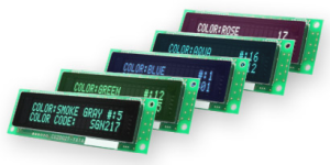
Color Filters
Noritake Itron offers 5 colors (gray, blue, green, aqua and rose) in 11 popular VFD module display sizes. Additional colors and sizes are available upon request