GT-CP Basic Code Set and Command Set
1 Basic Code Set
1.1 Character Code
Range: 0x20 – 0xFF, 2-byte character codes, or 1-4 byte UTF-8 byte sequences
Purpose: Draw a character at the current cursor position.
A 6×8, 8×16, 12×24, or 16×32 font size can be selected with Set Font Size.
Scalable fonts are also available with built-in outline fonts. (See Set Outline Font Size)
To use 2-byte characters, follow the Display 2-byte Characters guide.
GT-CP modules have the following built-in 2-byte fonts:
| Font Type | Code Type | First Byte | Second Byte |
|---|---|---|---|
| Japanese | JIS X0208 (Shift-JIS) |
0x81 ≤ c1 ≤ 0x9F 0xE0 ≤ c1 ≤ 0xEF |
0x40 ≤ c2 ≤ 0x7E 0x80 ≤ c2 ≤ 0xFC |
| Korean | KSC5601-87 | 0xA1 ≤ c1 ≤ 0xFE | 0xA1 ≤ c2 ≤ 0xFE |
| Simplified Chinese | GB2312-80 | 0xA1 ≤ c1 ≤ 0xFE | 0xA1 ≤ c2 ≤ 0xFE |
| Traditional Chinese | Big-5 | 0xA1 ≤ c1 ≤ 0xFE | 0x40 ≤ c2 ≤ 0x7E 0xA1 ≤ c2 ≤ 0xFE |
UTF-8 character code format can also be used by setting Set Font Table to 0xFE.
Note:
· This command only affects the currently-selected window.
· If the character size exceeds the current window size, the command is ignored.
1.2 Control Code
1.2.1 Backspace
Command Code: [0x08]
Purpose: Move cursor one character space to the left.
Behavior:
In Set Overwrite Mode (MD1) or Set Vertical Scroll Mode (MD2):
| Cursor Position | Display Operation Sequence | |
|---|---|---|
| X Direction | Y Direction | |
| There is space for a character on the left side. | – | 1. Cursor moves to the left by one character. |
| No space for a character on the left end. | Space for a character one line above. | 1. Cursor moves to the right end of next upper line. |
| No space for a character one line above. | 1. Cursor does not move. | |
In Set Horizontal Scroll Mode (MD3):
| Cursor Position | Display Operation Sequence | |
|---|---|---|
| X Direction | Y Direction | |
| There is space for a character on the left side. | – | 1. Cursor moves to the left by one character. |
| No space for a character on the left-most end. | – | 1. Cursor does not move. |
Note:
· This command only affects the currently-selected window.
1.2.2 Horizontal Tab
Command Code: [0x09]
Purpose: Move cursor to the right by one character width.
Behavior:
In Set Overwrite Mode (MD1):
| Cursor Position | Display Operation Sequence | |
|---|---|---|
| X Direction | Y Direction | |
| There is space for a character on the right side. | – | 1. Cursor moves to the right by one character. |
| No space for a character on the right side. | There is space for a character on the next line. | 1. Cursor moves to the left-most end of the next line. |
| No space for a character on the next line. | 1. Cursor moves to the left-most end of the top line. | |
In Set Vertical Scroll Mode (MD2):
| Cursor Position | Display Operation Sequence | |
|---|---|---|
| X Direction | Y Direction | |
| There is space for a character on the right side. | – | 1. Cursor moves to the right by one character. |
| No space for a character on the right side. | There is space for a character on the next line. | 1. Cursor moves to the left-most end of the next line. |
| No space for a character on the next line. | 1. Display contents are scrolled up the required number of pixels 2. Bottom line is cleared. 3. Cursor moves to the left-most end of the bottom line. |
|
In Set Horizontal Scroll Mode (MD3):
| Cursor Position | Display Operation Sequence | ||
|---|---|---|---|
| X Direction | Y Direction | ||
| There is space for a character on the right side. | Not at right-most end. | – | 1. Cursor moves to the right by one character. |
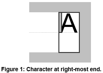
| At right-most end (refer to Figure 1). | 1. Set Horizontal Scroll Mode ON. | ||
| No space for a character on the right side. | – | – | 1. Contents on current line scroll left until sufficient space for a character is available on the right side. 2. Cursor moves to the left edge of newly-created space. 3. Set Horizontal Scroll Mode ON. |
Note:
· This command only affects the currently-selected window.
1.2.3 Line Feed
Command Code: [0x0A]
Purpose: Move cursor down to the next line.
Behavior:
In Set Overwrite Mode (MD1):
| Cursor Position | Display Operation Sequence | |
|---|---|---|
| X Direction | Y Direction | |
| – | There is space for a character on the next line. | 1. Cursor moves to the same X position on the next line. |
| No space for a character on the next line. | 1. Cursor moves to the X position on the top line. | |
In Set Vertical Scroll Mode (MD2):
| Cursor Position | Display Operation Sequence | |
|---|---|---|
| X Direction | Y Direction | |
| – | There is space for a character on the next line. | 1. Cursor moves to the same X position on the next line. |
| No space for a character on the next line. | 1. Display contents are scrolled up to the required number of pixels 2. Bottom line is cleared. 3. Cursor does not move. |
|
In Set Horizontal Scroll Mode (MD3) or Set Horizontal Scroll Mode ON (MD5) the cursor does not move.
Note:
· This command only affects the currently-selected window.
1.2.4 Home Position
Command Code: [0x0B]
Purpose: Move cursor to the top-left position on the screen at (0, 0), also known as the home position.
Note:
· This command only affects the currently-selected window.
1.2.5 Carriage Return
Command Code: [0x0D]
Purpose: Move cursor to the left-most end of the current character line.
Note:
· This command only affects the currently-selected window.
1.2.6 Display Clear
Command Code: [0x0C]
Purpose: Clear (background color fill) the entire display and move cursor to the Home Position.
Note:
· This command only affects the currently-selected window.
1.2.7 Line Clear
Command Code: [0x18]
Purpose: Clear (background color fill) the current character line and move cursor to the left-most end of the current line (aka a Carriage Return).
Note:
· This command only affects the currently-selected window.
1.2.8 Line-end Clear
Command Code: [0x19]
Purpose: Clear (background color fill) the current character line between the current cursor position and the right-most end of the current character line.
Note:
· This command only affects the currently-selected window.
2 Command Set
2.1 General Commands
2.1.1 Set Display Brightness
Command Code: [0x1F, 0x58, brightness]
Parameters:
| brightness | Brightness level setting. |
Range: 
Default: brightness=0xFF or MSW setting
Purpose: Set the display’s brightness level.

2.1.2 Initialize Display
Command Code: [0x1B, 0x40]
Purpose: Reset settings and clear the entire display screen.
Notes:
· Settings reset to their default values.
· Jumper settings are NOT reloaded.
· Receive buffer contents remain in memory.
· General-purpose I/O port settings persist.
· Settings not reset by this command can only be reset with a power cycle or the “Exit user setup mode” command.
2.1.3 Set Cursor Position
Command Code: [0x1F, 0x24, xPosL, xPosH, yPosL, yPosH]
Parameters:
| xPosL | X position | lower byte (1 pixel / unit) |
| xPosH | X position | upper byte (1 pixel / unit) |
| yPosL | Y position | lower byte (1 pixel / unit) |
| yPosH | Y position | lower byte (1 pixel / unit) |
Range: 
Purpose: Move cursor to the specified (X, Y) position on display memory.
Notes:
· If the specified position (X and/or Y) is outside the defined display area, the display will ignore the command and not change the cursor position.
· This command will affect the currently selected window.
2.1.4 Set Screen Write Mode
Command Code: [0x1F, 0x28, 0x77, 0x10, mode]
Parameters:
| mode | The desired screen write mode. |
Range: 
Settings:
| mode=0x00 | [Display Screen Mode] Display commands and actions are valid within the display or hidden area, depending on cursor position. |
| mode=0x01 | [All Screen Mode] Display commands and actions are valid over the entirety of display memory. |
Default: mode=0x00 or MSW setting
Purpose: Set the desired screen write mode.
Notes:
- This setting is only applicable for the base-window.
2.1.5 Reverse Display
Command Code: [0x1F, 0x72, reverse]
Parameters:
| reverse | Set reverse display ON or OFF. |
Range: 
Settings:
| reverse=0x00 | Set reverse OFF. |
| reverse=0x00 | Set reverse ON. |
Default: reverse=0x00 or MSW setting
Purpose: Turn reverse display mode ON or OFF for character and image drawing.
Notes:
· Changing this setting only affects subsequent characters and images drawn on screen.
· Content currently displayed on screen is not affected.
· When reverse display mode is ON:
o Background and foreground colors are flipped on text and monochrome images. Background to foreground and vice versa.
o Colors are inverted on color images (including 2-color monochrome BMP data)
· When reverse display mode is OFF, colors are displayed as expected.
2.1.6 Set Write Mixture Display Mode
Command Code: [0x1F, 0x77, mode]
Parameters:
| mode | Set desired write mixture mode. |
Range: 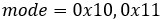
Settings:
| mode=0x10 | [Normal Write Mode] Background pixels overwrite existing display memorydata. |
| mode=0x11 | [Thru Write Mode] Background pixels do not overwrite existing displaymemory data, leaving the currently displayed pixelunchanged. This effectively makes background pixels“transparent”. |
Default: mode=0x10 or MSW setting
Purpose: Set the desired write mixture mode.
Notes:
· For color images, any black pixels are treated as background.
· Refer to Color Combination section for details.
2.1.7 Turn Display ON/OFF
Command Code: [0x1F, 0x28, 0x61, 0x40, power]
Parameters:
| power | Turn display ON/OFF |
Settings:
| power | Function |
|---|---|
| 0x00 | Display Power OFF |
| 0x01 | Display Power ON |
| 0x80 | Display Power OFF, turn ON when touched. |
Default: 0x01 (Display Power ON)
Purpose: Turn the display ON, OFF, or set the display to turn on when screen is touched.
Notes:
· Display can also be turned from OFF to ON with the Initialize Display command.
2.1.8 Set Power Saving Mode
Command Code: [0x1F, 0x28, 0x61, 0x48, 0x01, wakeup]
Parameters:
| wakeup | Desired display wakeup method. |
Settings:
|
wakeup |
||||||||
| b7 | b6 | b5 | b4 | b3 | b2 | b1 | b0 | GPIO15 wakeup condition |
| 0 | – | – | 0 | 0 | 0 | 0 | 0 | No wakeup on GPIO15 input |
| 0 | 0 | 0 | 1 | 0 | 0 | 0 | 0 | Wakeup on GPIO15 LOW level |
| 0 | 1 | 0 | 1 | 0 | 0 | 0 | 0 | Wakeup on GPIO15 falling edge |
| 0 | 0 | 1 | 1 | 0 | 0 | 0 | 0 | Wakeup on GPIO15 HIGH level |
| 0 | 1 | 1 | 1 | 0 | 0 | 0 | 0 | Wakeup on GPIO15 rising edge |
| 0 | 0 | 0 | 0 | 0 | 0 | 0 | 1 | Wakeup on touch |
Purpose: Configure the desired wakeup method and transition to power saving mode.
Notes:
- If wakeup=0x00, return to normal operation via external reset or power cycle.
· Communication interfaces do not function during power saving mode.
· Reduce current consumption by setting wakeup to GPIO15.
· Volatile setting values (e.g. brightness, GPIO input/output setting/level, etc.) are retained in power saving mode.
2.1.9 Set Touch Scan Period
Command Code: [0x1F, 0x28, 0x61, 0x49, period]
Parameters:
| period | Desired touch scan period. |
Range: 
Purpose: Set the desired touch scan period for Set Power Saving Mode.
Notes:
· Higher values result in lower power consumption and longer response times.
· This setting is not used if “wakeup on touch” is not set for Set Power Saving Mode. (b0=0)
2.1.10 Transmit Display Information
This command has been split up into smaller commands for simplicity.
All of the following commands are valid in user setup and normal modes.
2.1.10.1 Transmit Boot Version
Command Code: [0x1F, 0x28, 0x65, 0x40, 0x01]
Purpose: Transmit the display’s boot version information.
The following data is transmitted via the active interface.
| Transmitted Data | Hex | Data Length | Data Example |
| (1) Header | 28h | 1 byte | “(“ |
| (2) Identifier 1 | 65h | 1 byte | “e” |
| (3) Identifier 2 | 40h | 1 byte | “@” |
| (4) Data | 00h-FFh | 4 bytes | “0.00” |
2.1.10.2 Transmit Firmware Version
Command Code: [0x1F, 0x28, 0x65, 0x40, 0x02]
Purpose: Transmit the display’s firmware version information.
The following data is transmitted via the active interface.
| Transmitted Data | Hex | Data Length | Data Example |
| (1) Header | 28h | 1 byte | “(“ |
| (2) Identifier 1 | 65h | 1 byte | “e” |
| (3) Identifier 2 | 40h | 1 byte | “@” |
| (4) Data | 00h-FFh | 4 bytes | “1.62” |
Notes:
· The resulting firmware value relates to the actual firmware value like the following:
o “1.62”=F162
2.1.10.3 Transmit 2-byte Character Code
Command Code: [0x1F, 0x28, 0x65, 0x40, 0x10]
Purpose: Transmit the display’s currently selected 2-byte character code.
The following data is transmitted via the active interface.
| Transmitted Data | Hex | Data Length | Data Example |
| (1) Header | 28h | 1 byte | “(“ |
| (2) Identifier 1 | 65h | 1 byte | “e” |
| (3) Identifier 2 | 40h | 1 byte | “@” |
| (4) Data | 00h-FFh | 15 bytes | “JIS X208 L 100” |
2.1.10.4 Transmit Language Type
Command Code: [0x1F, 0x28, 0x65, 0x40, 0x11]
Purpose: Transmit the display’s currently selected language type.
The following data is transmitted via the active interface.
| Transmitted Data | Hex | Data Length | Data Example |
| (1) Header | 28h | 1 byte | “(“ |
| (2) Identifier 1 | 65h | 1 byte | “e” |
| (3) Identifier 2 | 40h | 1 byte | “@” |
| (4) Data | 00h-FFh | 15 bytes | “MULTI LANGUAGE” |
2.1.10.5 Transmit Memory Checksum
Command Code: [0x1F, 0x28, 0x65, 0x40, 0x20, start Addr, length]
Parameters:
| start Addr | Effective address is [start Addr * 0x10000] |
| length | Effective data length is [length * length * 0x10000] |
Purpose: Transmit the display’s memory checksum value.
The following data is transmitted via the active interface.
| Transmitted Data | Hex | Data Length | Data Example |
| (1) Header | 28h | 1 byte | “(“ |
| (2) Identifier 1 | 65h | 1 byte | “e” |
| (3) Identifier 2 | 40h | 1 byte | “@” |
| (4) Data | 00h-FFh | 4 bytes | 0x00, 0x6D, 0xA6, 0x97 |
2.1.10.6 Transmit General-purpose FROM2 Memory Checksum
Command Code: [0x1F, 0x28, 0x65, 0x40, 0x21, 0x00, startAddr3,startAddr2, startAddr1, startAddr0, size3, size2, size1, size0]
Parameters:
| start Addr | General-purpose FROM2 start address (32-bit) |
| size | Size of memory to calculate checksum (32-bit) |
Purpose: Transmit the display’s general-purpose memory checksum value.
The following data is transmitted via the active interface.
| Transmitted Data | Hex | Data Length | Data Example |
| (1) Header | 28h | 1 byte | “(“ |
| (2) Identifier 1 | 65h | 1 byte | “e” |
| (3) Identifier 2 | 40h | 1 byte | “@” |
| (4) Data | 00h-FFh | 4 bytes | 0x00, 0x00, 0x10, 0xEF |
2.1.10.7 Transmit Product Type
Command Code: [0x1F, 0x28, 0x65, 0x40, 0x30]
Purpose: Transmit the display’s product number.
The following data is transmitted via the active interface.
| Transmitted Data | Hex | Data Length | Data Example |
| (1) Header | 28h | 1 byte | “(“ |
| (2) Identifier 1 | 65h | 1 byte | “e” |
| (3) Identifier 2 | 40h | 1 byte | “@” |
| (4) Data | 00h-FFh | 15 bytes | “GT-C900PA ” |
2.1.10.8 Transmit Resolution Width
Command Code: [0x1F, 0x28, 0x65, 0x40, 0x40]
Purpose: Transmit the displays horizontal (X) resolution (in pixels)
The following data is transmitted via the active interface.
| Transmitted Data | Hex | Data Length | Data Example |
| (1) Header | 28h | 1 byte | “(“ |
| (2) Identifier 1 | 65h | 1 byte | “e” |
| (3) Identifier 2 | 40h | 1 byte | “@” |
| (4) Data | 00h-FFh | 3 bytes | “800” |
2.1.10.9 Transmit Resolution Height
Command Code: [0x1F, 0x28, 0x65, 0x40, 0x41]
Purpose: Transmit the displays vertical (Y) resolution (in pixels)
The following data is transmitted via the active interface.
| Transmitted Data | Hex | Data Length | Data Example |
| (1) Header | 28h | 1 byte | “(“ |
| (2) Identifier 1 | 65h | 1 byte | “e” |
| (3) Identifier 2 | 40h | 1 byte | “@” |
| (4) Data | 00h-FFh | 3 bytes | “480” |
2.1.10.10Transmit Touch Setting Package Name
Command Code: [0x1F, 0x28, 0x65, 0x40, 0x70]
Purpose: Transmit the name of the display’s active touch setting package.
The following data is transmitted via the active interface.
| Transmitted Data | Hex | Data Length | Data Example |
| (1) Header | 28h | 1 byte | “(“ |
| (2) Identifier 1 | 65h | 1 byte | “e” |
| (3) Identifier 2 | 40h | 1 byte | “@” |
| (4) Data | 00h-FFh | 15 bytes | “Noritake ” |
2.1.10.11Transmit Touch Setting Package ID
Command Code: [0x1F, 0x28, 0x65, 0x40, 0x71]
Purpose: Transmit for ID number of the display’s active touch setting package.
The following data is transmitted via the active interface.
| Transmitted Data | Hex | Data Length | Data Example |
| (1) Header | 28h | 1 byte | “(“ |
| (2) Identifier 1 | 65h | 1 byte | “e” |
| (3) Identifier 2 | 40h | 1 byte | “@” |
| (4) Data | 00h-FFh | 4 bytes | “0003” |
2.1.10.12Transmit Touch Gain Setting
Command Code: [0x1F, 0x28, 0x65, 0x40, 0x72]
Purpose: Transmit the display’s currently selected touch gain value.
The following data is transmitted via the active interface.
| Transmitted Data | Hex | Data Length | Data Example |
| (1) Header | 28h | 1 byte | “(“ |
| (2) Identifier 1 | 65h | 1 byte | “e” |
| (3) Identifier 2 | 40h | 1 byte | “@” |
| (4) Data | 00h-FFh | 1 byte | “0x06” |
2.1.10.13Transmit Touch Threshold Setting
Command Code: [0x1F, 0x28, 0x65, 0x40, 0x73]
Purpose: Transmit the display’s currently selected touch threshold value.
The following data is transmitted via the active interface.
| Transmitted Data | Hex | Data Length | Data Example |
| (1) Header | 28h | 1 byte | “(“ |
| (2) Identifier 1 | 65h | 1 byte | “e” |
| (3) Identifier 2 | 40h | 1 byte | “@” |
| (4) Data | 00h-FFh | 1 byte | “0x50” |
2.2 Character Drawing Commands
2.2.1 Set International Font
Command Code: [0x1B, 0x52, type]
Parameters:
| type | Set desired international font. |
Settings:
| type | Font Set |
|---|---|
| 0x00 | America |
| 0x01 | France |
| 0x02 | Germany |
| 0x03 | England |
| 0x04 | Denmark 1 |
| 0x05 | Sweden |
| 0x06 | Italy |
| 0x07 | Spain1 |
| 0x08 | Japan |
| 0x09 | Norway |
| 0x0A | Denmark2 |
| 0x0B | Spain2 |
| 0x0C | Latin America |
| 0x0D | Korea |
Default: type=0x00 or MSW setting
Purpose: Set desired international font.
Notes:
· Characters already drawn to the display are not affected.
· If UTF-8 input is selected, this setting is not used. (see Set Font Table)
· This command changes the first 127 characters in the font set. More information on font set changes.
2.2.2 Set Font Table
Command Code: [0x1B, 0x74, type]
Parameters:
| type | Set desired font table. |
Settings:
| type | Font Table |
|---|---|
| 0x00 | PC437(USA – Euro std) |
| 0x01 | Katakana – Japanese |
| 0x02 | PC850 (Multilingual) |
| 0x03 | PC860 (Portuguese) |
| 0x04 | PC863 (Canadian-French) |
| 0x05 | PC865 (Nordic) |
| 0x10 | WPC1252 |
| 0x11 | PC866 (Cyrillic #2) |
| 0x12 | PC852 (Latin 2) |
| 0x13 | PC858 |
| 0xFE | UTF-8 input |
| 0xFF | User-defined font table |
Default: type=0x00 or MSW setting
Purpose: Select desired font table.
Notes:
· Already displayed characters are not affected.
· This command changes character 128 and onward in the font set.
2.2.3 Set Overwrite Mode
Command Code: [0x1F, 0x01]
Purpose: Set display to overwrite mode.
This is the default character behavior mode.
Characters are drawn on screen from left to right and will overwrite any previously written character at the cursor position.
If the cursor reaches the right-most end of the screen, it will perform a carriage return line feed operation and move to the left-most position on the next character line.
If the cursor reaches the bottom-right of the screen, it will move back to the top-left home position on the screen.
More detailed behavior for overwrite mode is described below:
| Cursor Attributes | Figure Number | Display Operation Sequence | |
|---|---|---|---|
| X Direction | Y Direction | ||
|
Space for a character on the right side. |
Space for a character at current cursor position. | ① | 1. Display character at cursor position. 2. Perform a Horizontal Tab (HT). |
| No space for a character at current cursor position. | ② | 1. Cursor moves to the left end of top line (OP3). 2. Display character at cursor position. 3. Perform a Horizontal Tab (HT). |
|
|
No space for a character on the right side. |
Space for a character on next line. | ③ | 1. Display space at cursor (OP1). 2. Cursor moves to the left end of next line (OP4). 3. Display character at new cursor position. 4. Perform a Horizontal Tab (HT). |
| No space for a character on next line. | ④ | 1. Display space at cursor (OP1). 2. Cursor moves to the left end of top line (OP2). 3. Display character at new cursor position. 4. Perform a Horizontal Tab (HT). |
|
| No space for a character at current cursor position. | ⑤ | 1. Cursor moves to the left end of top line (OP2). 2. Display character at new cursor position. 3. Perform a Horizontal Tab (HT). |
|
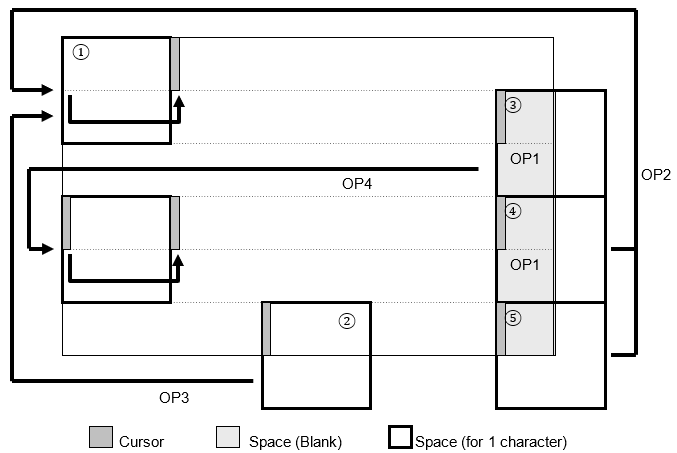
2.2.4 Set Vertical Scroll Mode
Command Code: [0x1F, 0x02]
Purpose: Set display to vertical scroll mode.
Characters are drawn on screen from left to right and will overwrite any previously written character at the cursor position.
If the cursor reaches the right-most end of the screen, it will perform a carriage return line feed operation and move to the left-mostposition on the next character line.
If the cursor reaches the bottom-right of the screen, it will move back to the left-most position on the same line. Additionally, the entiredisplay is vertically scrolled n pixels. (n ischaracter line height)
More detailed behavior for overwrite mode is described below:
| Cursor Attributes | Figure Number | Display Operation Sequence | |
|---|---|---|---|
| X Direction | Y Direction | ||
|
Space for character on right side. |
Space for a character at current cursor position. | ① | 1. Display a character at cursor. 2. Perform a Horizontal Tab (HT) (OP4). |
| No space for a character at current cursor position. | ② | 1. Display contents are scrolled up the required number of pixels. 2. Bottom line is cleared. 3. Cursor moves to an open upper position (OP3). 4. Display character at new cursor position. 5. Perform a Horizontal Tab (HT). |
|
|
No space for character on right side. |
Space for a character in next lower line. | ③ | 1. Display space at cursor (OP1). 2. Cursor moves to left end of next line (OP2). 3. Display character at new cursor position. 4. Performa a Horizontal Tab (HT). |
| No space for a character in next lower line. | ④ | 1. Display space at cursor (OP1). 2. Display contents are scrolled up the required number of pixels. 3. Bottom line is cleared. 4. Cursor moves to left end of bottom line (OP5). 5. Display character at new cursor position. 6. Perform a Horizontal Tab (HT). |
|
| No space for a character at current cursor position. | ⑤ | 1. Display contents are scrolled up the required number of pixels. 2. Bottom line is cleared. 3. Cursor moves to left end of bottom line (OP5). 4. Display character at new cursor position. 5. Perform a Horizontal Tab (HT). |
|
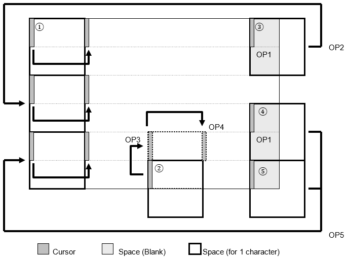
2.2.5 Set Horizontal Scroll Mode
Command Code: [0x1F, 0x03]
Purpose: Set display to horizontal scroll mode.
Characters are drawn on screen from left to right and will overwrite any previously written character at the cursor position.
If the cursor reaches the right-most end of the screen, it will not move. Instead, the currently displayed characters will horizontally shift to the left enough pixels to draw another character at the cursor position. This is the same behavior as Set Static Horizontal Scroll Mode.
More detailed behavior for overwrite mode is described below:
| Cursor Attributes | Figure Number | Display Operation Sequence | ||
|---|---|---|---|---|
| X Direction | Y Direction | |||
|
Space for a character on right side. |
Not right end. |
– |
① | 1. Display character at cursor position. 2. Perform a Horizontal Tab (HT) (OP2). |
| Right end (Refer to Figure 1). | – | 1. Display character at cursor position. 2. Shift to static scroll. |
||
| – | No space for a character at current cursor position. | ② | No action. Cursor does not move. | |
|
No space for a character on right side. |
– | – | ③ | 1. Contents of current line scroll to left until sufficient space for character is available at the right end (OP3). 2. Cursor moves to left edge of newly-created space(OP1). 3. Display character at cursor. 4. Shift to static scroll. |
| – | No space for a character at current cursor position. | ④ | No action. Cursor does not move. | |
2.2.6 Set Static Horizontal Scroll Mode
Command Code: [0x1F, 0x05]
Purpose: Set static display to horizontal scroll mode.
Cursor is fixed to the right-hand side of the active window. Currently displayed characters shift to the left by one character-sized column. Character is drawn at cursor position.
2.2.7 Set Font Size
Command Code: [0x1F, 0x28, 0x67, 0x01, size]
Parameters:
| size | Font size selection. |
Settings:
| size | Font Size |
|---|---|
| 0x00 | Outline font* |
| 0x01 | 6×8 pixel character |
| 0x02 | 8×16 pixel character |
| 0x03 | 12×24 pixel character |
| 0x04 | 16×32 pixel character |
Default: size=0x01 or MSW setting
Purpose: Set the font size for 1-byte characters.
Notes:
* This must be set first before configuring outline font size. (see Outline Font Setup)
2.2.8 Set 2-byte Character
Command Code: [0x1F, 0x28, 0x67, 0x02, enable]
Parameters:
| enable | Set 2-byte character display ON or OFF. |
Settings:
| enable | Function |
|---|---|
| 0x00 | 2-byte character mode OFF |
| 0x01 | 2-byte character mode ON |
Default: enable=0x00 or MSW setting
Purpose: Set 2-byte character display ON or OFF.
Notes:
· This command is not used if UTF-8 input is selected. (refer to Set Font Table)
2.2.9 Set 2-byte Character Type
Command Code: [0x1F, 0x28, 0x67, 0x03, type]
Parameters:
| type | Desired 2-byte character type |
Settings:
| type | Function | Code Type |
|---|---|---|
| 0x00 | Japanese | JIS X0208 (Shift-JIS) |
| 0x01 | Korean | KSC5601-87 |
| 0x02 | Simplified Chinese | GB2312-80 |
| 0x03 | Traditional Chinese | Big-5 |
Purpose: Set desired 2-byte character type.
Notes:
· This command is not used if UTF-8 input is selected. (refer to Set Font Table)
2.2.10 Set User-supplied Font File Address and Size
Command Code: [0x1F, 0x28, 0x67, 0x07, addr0, addr1, addr2, addr3, size0, size1, size2, size3]
Parameters:
| addr[addr3:addr2:addr1:addr0] | Font file start address in general-purpose FROM2.(32-bit) |
| size[size3:size2:size1:size0] | Font file size is bytes. (32-bit) |
Range: 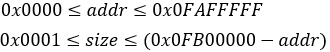
Purpose: Select a user-supplied font file via its address and size in general-purpose FROM2.
Notes:
· User-supplied font file is loaded when Set Outline Font Type is set to 0xFF.
· Maximum file size depends on the display being used.
o 4.3 inch display: 8MB max.
o Other GT-CP series displays: 32MB max.
· If the specified range is exceeded, this command is ignored.
2.2.11 Set Outline Font Type
Command Code: [0x1F, 0x28, 0x67, 0x08, type]
Parameters:
| type | Outline font type selection. |
Settings:
| type | Outline Font Type |
|---|---|
| 0x00 | Japanese |
| 0x01 | Korean |
| 0x02 | Simplified Chinese |
| 0x03 | Traditional Chinese |
| 0x80 | None (no outline font selected |
| 0xFF | User-supplied Font File |
Default: 0x80 (None)
Purpose: Set desired outline font type.
Notes:
· Specific commands must be executed before outline font can be used. Refer to the outline font guide for detailed outline font setup instructions.
· This command must be re-executed after a power cycle or initialization command.
- If font loading fails, type is set to 0x00 (None).
· If type=0x01 (Korean), a small number of characters available in the built-in pixel font are not available in the built-in outline font.
· After this command is executed, the outline font data is read. This will take several sections. Do not send any data during this time.
2.2.12 Set Outline Font Size
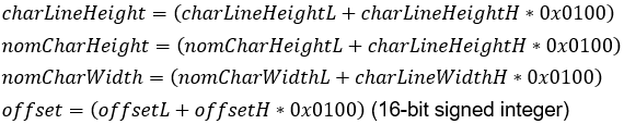
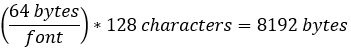
Command Code: [0x1F, 0x28, 0x67, 0x06, charLineHeightL, charLineHeightH, nomCharHeightL, nomCharHeightH, nomCharWidthL, nomCharWidthH, offsetL, offsetH]
Parameters:
| charLineHeight | Height of character line in pixels. When multiple lines of text are displayed, this parameter determines vertical line pitch. |
| nomCharHeight | Nominal character height in pixels. Normally less than charLineHeight. |
| nomCharWidth | Nominal character width in pixels. Normally less than charLineHeight. |
| offset | Baseline’s Y offset from cursor position in pixels. Positive values place baseline below cursor. Negative values place baseline above cursor. |
Range:
 If charLineHeight is zero, the previous setting or default setting (64)is used.
 If nomCharHeight is zero, the value is set to nomCharWidth.
 If nomCharWidth is zero, the value is set to nomCharHeight.
 If offset is higher or lower than range, value is capped.
If offset is zero, offset is automatically calculatedrelative to the other parameters to vertically center the text.
If offset is 0x8000, zero offset.
Default: charLineHeight = nomCharHeight = nomCharWidth=64
offset=0
Purpose: Set outline character size, line spacing, and alignment.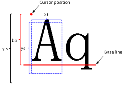
Notes:
· If nomCharHeight and nomCharwidth are both zero, their values are automatically calculated relative to charLineHeight.
2.2.13 Set Font Width
Command Code: [0x1F, 0x28, 0x67, 0x04, width]
Parameters:
| width | Set the desired character width. |
Settings:
The two font width settings are:
| Fixed-width | All characters are displayed with constant spacing. |
| Proportional | All characters are displayed with varied spacing. Width=left blank + character width + right blank |
Font width settings affect different size pixel characters is various ways.
| 6×8 Pixel Character | ||||
| width | Width Setting | Left Blank Pixels |
Right Blank Pixels |
Space (0x20) Character Width |
| 00h | Fixed-width | 0 | 0 | 6 |
| 02h | Proportional 1 | 0 | 1 | 2 |
| 03h | Proportional 2 | 1 | 1 | 2 |
| 04h | Proportional 3 | 2 | 2 | 2 |
| 8×16 Pixel Character | ||||
| width | Width Setting | Left Blank Pixels |
Right Blank Pixels |
Space (0x20) Character Width |
| 00h | Fixed-width | 0 | 0 | 8 |
| 02h | Proportional 1 | 0 | 1 | 4 |
| 03h | Proportional 2 | 1 | 1 | 4 |
| 04h | Proportional 3 | 2 | 2 | 4 |
| 12×24 Pixel Character | ||||
| width | Width Setting | Left Blank Pixels |
Right Blank Pixels |
Space (0x20) Character Width |
| 00h | Fixed-width | 0 | 0 | 12 |
| 02h | Proportional 1 | 0 | 2 | 6 |
| 03h | Proportional 2 | 2 | 2 | 6 |
| 04h | Proportional 3 | 4 | 4 | 6 |
| 16×32 Pixel Character | ||||
| width | Width Setting | Left Blank Pixels |
Right Blank Pixels |
Space (0x20) Character Width |
| 00h | Fixed-width | 0 | 0 | 16 |
| 02h | Proportional 1 | 0 | 2 | 8 |
| 03h | Proportional 2 | 2 | 2 | 8 |
| 04h | Proportional 3 | 4 | 4 | 8 |
Example: 6×8 pixel character ‘I’ | width=0x03 (Proportional 2)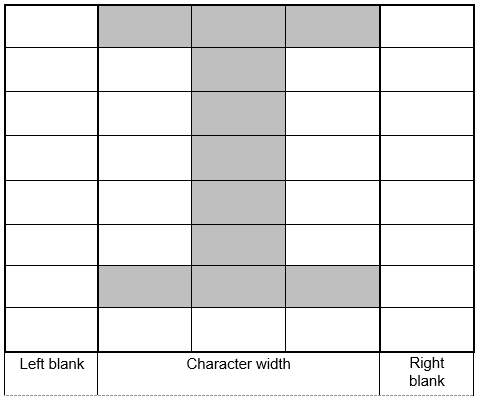
| Left blank |
Character width |
Right blank | ||
Default: width=0x00 (Fixed-width)
Purpose: Set the desired character width.
Notes:
· This command is applicable for pixel characters only, not outline font.
2.2.14 Define FROM User Font
Command Code: [0x1F, 0x28, 0x65, 0x13, table, data[0x80-1] …data[0x80-n]]
Parameters:
| table | Set the desired character table size to define. |
| data | User font data. |
Settings:
| table | Table Type |
|---|---|
| 0x01 | 6×8 pixel user table |
| 0x02 | 8×16 pixel user table |
| 0x03 | 12×24 pixel user table |
| 0x04 | 16×32 pixel user table |
Range:
 table=0x01 | data(0x80-1)…data(0x80-6)…data(0xFF-6)
 table=0x02 | data(0x80-1)…data(0x80-16)…data(0xFF-16)
 table=0x03 | data(0x80-1)…data(0x80-36)…data(0xFF-36)
 table=0x04 | data(0x80-1)…data(0x80-64)…data(0xFF-64)
Purpose: Define a user font for a user table consisting of 1-byte character codes. This command defines all 128 characters at once. (with character codes 0x80 – 0xFF) Partial font definitions are not possible.
Notes:
· User font tables for each font size are set to 0x00 by default.
- This command is only valid in Start User Setup Mode.
· Data is not saved to FROM until End User Setup Mode is executed.
- Select FROM user font table with Set Font Table.
2.2.15 Define FROM Extension User Font
Command Code: [0x1F, 0x28, 0x65, 0x15, 0x01, 0x01, data[1] … data[65536]]
Parameters:
| data | FROM extension font data. (consult manufacturer for data format) |
Range: 
Purpose: Define the FROM extension user font.
Notes:
· This command is only valid in user setup mode.
· Data is not committed to FROM until user setup mode ends.
· FROM extension font is empty by default.
2.2.16 Delete FROM Extension User Font
Command Code: [0x1F, 0x28, 0x65, 0x15, 0x01, 0x00]
Purpose: Delete the FROM extension user font.
Note:
· This command is only valid in user setup mode.
· Data is not committed to FROM until user setup mode ends.
2.2.17 Set FROM Extension Font
Command Code: [0x1F, 0x28, 0x67, 0x05, font]
Parameters:
| font | Set the desired FROM extension font. |
Settings:
| font | Setting |
|---|---|
| 0x00 | Normal Font |
| 0x01 – 0xFF | FROM Extension Font (if an FROM extension font isdefined) |
Default: font=0x00 (Normal Font)
Purpose: Set the desired FROM extension font.
2.2.18 Set Font Magnification
Command Code: [0x1F, 0x28, 0x67, 0x40, x, y]
Parameters:
| x | X magnification factor increases character width by afactor of x |
| y | Y magnification factor increases character height by afactor of y |
Range: 
Default: x=0x01 or MSW setting
y=0x01 or MSW setting
Purpose: Set the desired pixel character magnification.
2.2.19 Set Character Style
Command Code: [0x1F, 0x28, 0x67, 0x41, style]
Parameters:
| style | Set desired character style. |
Settings:
| style | Style Setting |
|---|---|
| 0x00 | Normal |
| 0x01 | Bold |
| 0x02 | Shadow |
| 0x03 | Bordering (highlight?) |
Range: 
Purpose: Set the desired pixel character style.
2.2.20 Set Character Color
Command Code: [0x1F, 0x28, 0x67, 0x50, red, green, blue]
Parameters:
| red | Red pixel brightness. |
| green | Green pixel brightness. |
| blue | Blue pixel brightness. |
Range: 
0x00 (OFF) … 0x7F (50%) … 0xFF (Maximum)
Default: red, green, blue=0xFF
Purpose: Set the desired character color.
2.2.21 Set Background Color
Command Code: [0x1F, 0x28, 0x67, 0x51, red, green, blue]
Parameters:
| red | Red pixel brightness. |
| green | Green pixel brightness. |
| blue | Blue pixel brightness. |
Range: 
0x00 (OFF) … 0x7F (50%) … 0xFF (Maximum)
Default: red, green, blue=0xFF
Purpose: Set the desired background color.
Notes:
· This setting is only valid when Set Background Color ON/OFF is ON.
2.2.22 Set Shadow and Border Color
Command Code: [0x1F, 0x28, 0x67, 0x52, red, green, blue]
Parameters:
| red | Red pixel brightness. |
| green | Green pixel brightness. |
| blue | Blue pixel brightness. |
Range: 
0x00 (OFF) … 0x7F (50%) … 0xFF (Maximum)
Default: red, green, blue=0xFF
Purpose: Set the desired shadow and border (highlight?) color.
Notes:
· This setting is only valid when shadow or bordering is set with Set Character Style.
· This setting is only valid for pixel characters.
2.2.23 Enable Background Color
Command Code: [0x1F, 0x28, 0x67, 0x58, 0x01]
Default: Background color is disabled by default.
Purpose: Enable background color.
Notes:
· Background color is not used if Set Write Mixture Display Mode is set to “Thru Write” mode. Background will be transparent instead.
2.2.24 Disable Background Color
Command Code: [0x1F, 0x28, 0x67, 0x58, 0x00]
Default: Background color is disabled by default.
Purpose: Disable background color. (Set background black)
2.3 User Character Commands
2.3.1 Enable User Characters
Command Code: [0x1B, 0x25, 0x01]
Purpose: Enable the use of 6×8, 8×16, 12×24, and 16×32 pixel user characters.
2.3.2 Disable User Characters
Command Code: [0x1B, 0x25, 0x00]
Purpose: Disable the use of 6×8, 8×16, 12×24, and 16×32 pixel user characters.
2.3.3 Define User Character
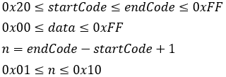
Command Code: [0x1B, 0x26, charType, startCode, endCode, [width[1], data[1]]…[width[n], data[n]]]
Parameters:
| charType | Desired character type to define. |
| startCode | Starting character code. |
| endCode | Ending character code. |
| width | Width of character(s) in pixels. |
| data | Character definition data. |
Settings:
| charType | Type |
|---|---|
| 0x01 | 6×8 pixel character |
| 0x02 | 8×16 pixel character |
| 0x03 | 12×24 pixel character |
| 0x04 | 16×32 pixel character |
Range:
6×8 pixel character:
8×16 pixel character:
12×24 pixel character:
16×32 pixel character:
Purpose: Define a certain number of user characters into RAM. Up to 16 user characters can be defined for each font size. To display a user character, the user character must be defined and user characters must be enabled with Enable User Characters.
Notes:
· If the maximum number of characters is defined, another character can only be defined if an existing user character is deleted first with Delete User Character.
· User characters are valid until:
o The characters are redefined
o Initialize Display is executed
o Display is power cycled
- If width is smaller than the set character width, the remaining space is left blank.
· If a user character is drawn on the display and later re-defined, the existing character on screen does not change.
· User characters can be saved to FROM with Save User Character.
2.3.4 Delete User Character
Command Code: [0x1B, 0x3F, charType, charCode]
Parameters:
| charType | Character type of character to delete. |
| charCode | Character code to delete. |
Settings:
| charType | Type |
|---|---|
| 0x01 | 6×8 pixel character |
| 0x02 | 8×16 pixel character |
| 0x03 | 12×24 pixel character |
| 0x04 | 16×32 pixel character |
Range: 
Purpose: Delete a single user character.
Notes:
· If the user character is already drawn on the screen, it is not affected when the user character is deleted.
· Once a user character is deleted, the built-in character is used instead.
· This command is ignored if the user character using charCodein charType is not defined yet.
2.3.5 Define 16×16 User Character
Command Code: [0x1F, 0x28, 0x67, 0x10, charCodeH, charCodeL, data[1]…data[32]]
Parameters:
| charCode[charCodeH:charCodeL] | Desired 2-byte character to define. |
| data | Character definition data. |
Range: 
charCode value depends on the currently set language.
| Language | Encoding | charCodeH | charCodeL |
|---|---|---|---|
| Japanese | JIS X0208 (SHIFT-JIS) | 0xEC | 0x40 ≤ charCodeL ≤ 0x4F |
| Korean | KSC5601-87 | 0xFE | 0xA1 ≤ charCodeL ≤ 0xB0 |
| Simplified Chinese | GB2312-80 | 0xFE | 0xA1 ≤ charCodeL ≤ 0xB0 |
| Traditional Chinese | Big-5 | 0xFE | 0xA1 ≤ charCodeL ≤ 0xB0 |

Purpose: Defined a 2-byte 16×16 user character using character code specified by charCode. Data should be in column format and will be stored sequentially starting with the left-most column.
Notes:
· A maximum of 16 characters can be defined.
· User character data is temporarily stored in RAM using this command. This data can be saved to FROM with Save User Character.
2.3.6 Delete 16×16 User Character
Command Code: [0x1F, 0x28, 0x67, 0x11, charCodeH, charCodeL]
Parameters:
| charCode[charCodeH:charCodeL] | Desired 2-byte character to delete. |
Range:
charCode value depends on the currently set language.
| Language | Encoding | charCodeH | charCodeL |
|---|---|---|---|
| Japanese | JIS X0208 (SHIFT-JIS) | 0xEC | 0x40 ≤ charCodeL ≤ 0x4F |
| Korean | KSC5601-87 | 0xFE | 0xA1 ≤ charCodeL ≤ 0xB0 |
| Simplified Chinese | GB2312-80 | 0xFE | 0xA1 ≤ charCodeL ≤ 0xB0 |
| Traditional Chinese | Big-5 | 0xFE | 0xA1 ≤ charCodeL ≤ 0xB0 |
Purpose: Delete a 2-byte 16×16 user character at the character code specified by charCode.
2.3.7 Define 32×32 User Character
Command Code: [0x1F, 0x28, 0x67, 0x14, charCodeH, charCodeL, data[1]…data[128]]
Parameters:
| charCode[charCodeH:charCodeL] | Desired 2-byte character to define. |
| data | Character definition data. |
Range:
charCode value depends on the currently set language.
| Language | Encoding | charCodeH | charCodeL |
|---|---|---|---|
| Japanese | JIS X0208 (SHIFT-JIS) | 0xEC | 0x40 ≤ charCodeL ≤ 0x4F |
Purpose: Defined a 2-byte 32×32 user character using character code specified by charCode. Data should be in column format and will be stored sequentially starting with the left-most column.
Notes:
· A maximum of 16 characters can be defined.
· User character data is temporarily stored in RAM using this command. This data can be saved to FROM with Save User Character.
· This command is invalid if the current language is not set to Japanese.
2.3.8 Delete 32×32 User Character
Command Code: [0x1F, 0x28, 0x67, 0x15, charCodeH, charCodeL]
Parameters:
| charCode[charCodeH:charCodeL] | Desired 2-byte character to delete. |
Range:
charCode value depends on the currently set language.
| Language | Encoding | charCodeH | charCodeL |
|---|---|---|---|
| Japanese | JIS X0208 (SHIFT-JIS) | 0xEC | 0x40 ≤ charCodeL ≤ 0x4F |
Purpose: Delete a 2-byte 32×32 user character at the character code specified by charCode.
Notes:
· This command is invalid if the current language is not set to Japanese.
2.3.9 Save User Characters
Command Code: [0x1F, 0x28, 0x65, 0x11, size]
Parameters:
| size | Size of user characters to save. |
Settings:
| size | User Character Size |
|---|---|
| 0x01 | 6×8 |
| 0x02 | 8×16 |
| 0x03 | 16×16 |
| 0x04 | 16×32 |
| 0x05 | 32×32 |
| 0x06 | 12×24 |
Purpose: Transfer user defined characters from RAM to FROM.
Notes:
· Transfer data back to RAM with Restore User Characters
- This command is only valid in Start User Setup Mode.
· Data is not saved to FROM until End User Setup Mode.
2.3.10 Restore User Characters
Command Code: [0x1F, 0x28, 0x65, 0x21, size]
Parameters:
| size | Size of user characters to restore. |
Settings:
| size | User Character Size |
|---|---|
| 0x01 | 6×8 |
| 0x02 | 8×16 |
| 0x03 | 16×16 |
| 0x04 | 16×32 |
| 0x05 | 32×32 |
| 0x06 | 12×24 |
Purpose: Transfer user defined characters from FROM to RAM.
Notes:
· This command is ignored if the specified character size user characters are not saved to FROM.
· This command is valid in Start User Setup Mode and normal mode.
2.4 Display Action Commands
2.4.1 Blink Action
Command Code: [0x1F, 0x28, 0x61, 0x11, pattern, normalTime, blankTime, numCycles]
Parameters:
| pattern | Desired blink pattern. |
| normalTime | Normal display time. |
| blankTime | Blank display time. |
| numCycles | Number of blink cycles. |
Settings:
| pattern | Type |
|---|---|
| 0x00 | Normal |
| 0x01 | Blink (alternate between Normal and Blank) |
| 0x02 | Reserved. |
| numCycles | Behavior |
|---|---|
| 0x00 | Blink continuously until numCycles is greater than0x00 or display init. |
| 0x01 – 0xFF | Repeat blink action numCycles times |
Range: 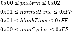
Purpose: Set and use the “blink” display action. The resulting pattern is determined by the value of pattern. The “blink” display action should alternate between display ON and display OFF states.
Notes:
· This command does not affect display memory.
· Command/data processing is suspended until action is complete.
2.4.2 Scroll Action
Command Code: [0x1F, 0x28, 0x61, 0xA0, xShiftL, xShiftH,yShiftL, yShiftH, repsL, repsH, interval]
Parameters:
| xShift[xShiftH:xShiftL] | Number of pixels to scroll to the left. |
| yShift[yShiftH:yShiftL] | Number of pixels to scroll down. |
| reps[repsH:repsL] | Number of times to repeat the scroll action. |
| interval | Pixel scroll interval. Larger value means slowerscroll. pixelShiftTime is the time it takes to scroll one pixelin ms. |
Purpose: Scroll/shift the display contents the desired number of pixels to theleft and down.
Examples:
1. Scroll display contents 1 pixel to the left. [xShift=0x01, yShift=0x00]
2. Scroll display contents 1 pixel to the right.
a. For 800×480: [xShift=Xdots– 1=0x063F, yShift=0x00]
b. For 480×272: [xShift=Xdots– 1=0x03BF, yShift=0x00]
This will scroll the display contents [Xdots– 1 pixel] to the left. However, it will appear as if the contents have shifted one pixel to the right.
Notes:
· Command/data processing is suspended until action is complete.
2.4.3 Curtain Action
Command Code: [0x1F, 0x28, 0x61, 0xA2, direction, speed, red, green, blue]
Parameters:
| direction | Desired direction for the curtain action. |
| speed | |
| red | Red pixel brightness. |
| green | Green pixel brightness. |
| blue | Blue pixel brightness. |
Settings:
| direction | Action Direction |
|---|---|
| 0x00 | From left to right. |
| 0x01 | From right to left. |
| 0x02 | Split from the center to the left and right. |
| 0x03 | From the left and right to the center. |
Range: 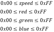
Purpose: Execute a curtain action on the display. The curtain action moves a“curtain” with color specified by [red, green, blue] on the screen. The way the curtain moves is specified with the direction parameter.
Example: Close the “curtains” from the left and right. [direction=0x03]
Notes:
· This command only affects the visible display area.
· Command/data processing is suspended until action is complete.
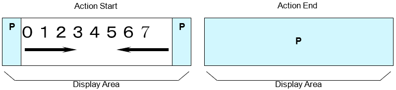
2.4.4 Spring Action
Command Code: [0x1F, 0x28, 0x61, 0xA3, direction, speed, xPosL, xPosH, yPosL, yPosH]
Parameters:
| direction | Desired direction for the spring action. |
| speed | |
| xPos[xPosH:xPosL] | X position of display memory for spring action. |
| yPos[yPosH:yPosL] | Y position of display memory for spring action. |
Settings:
| direction | Action Direction |
|---|---|
| 0x00 | From left to right. |
| 0x01 | From right to left. |
| 0x02 | Split from the center to the left and right. |
| 0x03 | From the left and right to the center. |
Range: 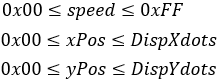
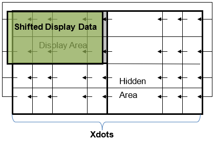
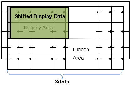
Purpose: Execute a spring action on the display. The spring action moves display data from the hidden area to the display area with a curtain-like animation. The display data to move is specified with [xPos, yPos].
Example: Open the “curtain” from the center to the left and right. [ direction=0x02]
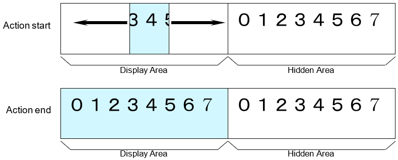
Notes:
· This command only affects the display area. (not the hidden area)
· Command/data processing is suspended until the action is complete.
2.4.5 Random Action
Command Code: [0x1F, 0x28, 0x61, 0xA4, type, speed, xPosL, xPosH, yPosL, yPosH]
Parameters:
| type | Desired direction for the spring action. |
| speed | |
| xPos[xPosH:xPosL] | X position of display memory for spring action. |
| yPos[yPosH:yPosL] | Y position of display memory for spring action. |
Settings:
| 15 | 5 | 8 | 13 | 1 | 2 | 3 | 4 | 3 | 5 | 7 | 9 | ||
| 1 | 12 | 4 | 6 | 12 | 13 | 14 | 5 | 5 | 7 | 9 | 11 | ||
| 9 | 7 | 16 | 2 | 11 | 16 | 15 | 6 | 7 | 9 | 11 | 13 | ||
| 14 | 3 | 11 | 10 | 10 | 9 | 8 | 7 | 9 | 11 | 13 | 15 | ||
| type=0x00 | type=0x01 | type=0x02 | |||||||||||
During the execution of Random Action, each 16×16 pixel area on the screen is split into sixteen 4×4 pixel cell grid. Each pixel transitions to the new display pattern relative to its assigned number. Pixel 1 is transitioned first while pixel 16 is last.
Range: 
Purpose: Execute the “Random” action on the display. This action moves display data from the hidden area to the display area by “randomly” transitioning pixels to the hidden area contents. This “random” transformation pattern is determined by the type parameter. The display data to move is specified with [xPos, yPos].
Example:
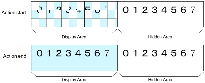
Notes:
· This action is completed in 16 steps.
· This command only affects the display area. (not the hidden area)
· Command/data processing is suspended until action is completed.
2.4.6 Fade-In Action
Command Code: [0x1F, 0x28, 0x61, 0xA5, speed, xPosL, xPosH, yPosL, yPosH]
Parameters:
| speed | Fade in speed. |
| xPos[xPosH:xPosL] | X position of display memory for spring action. |
| yPos[yPosH:yPosL] | Y position of display memory for spring action. |
Range: 
Purpose: Execute the fade-in action on the display. This action will gradually increase the display brightness to reveal the hidden display contents that was moved during the fade-in action.
Notes:
· This command only affects the display area. (not the hidden area)
· Command/data processing is suspended until action is completed.
2.4.7 Fade-Out Action
Command Code: [0x1F, 0x28, 0x61, 0xA6, speed]
Parameters:
| speed | Fade out speed. |
Range: 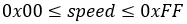
Purpose: Execute the fade-out action on the display. This action will gradually decrease the display brightness all the way down to 0.
Notes:
· This command only affects the display area. (not the hidden area)
· Command/data processing is suspended until action is completed.
2.5 Drawing Commands
2.5.1 Draw Pixel
Command Code: [0x1F, 0x28, 0x64, 0x10, pen, xPosL, xPosH, yPosL, yPosH]
Parameters:
| pen | Set pixel color to background or character color. |
| xPos[xPosH:xPosL] | Pixel X position. |
| yPos[yPosH:yPosL] | Pixel Y position. |
Settings:
| pen | Color |
|---|---|
| 0x00 | Background |
| 0x01 | Character |
Range: 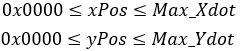
Purpose: Draw a pixel at the specified (x, y) position on the screen with the specified color (background or character).
Notes:
· This command only affects the currently-selected window.
· If any parameter is outside the display’s definable area, the command is cancelled and the remaining command data is treated as character code.
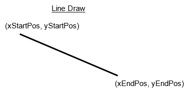
2.5.2 Draw Line
Command Code: [0x1F, 0x28, 0x64, 0x11, 0x00, pen, xStartPosL,xStartPosH, yStartPosL, yStartPosH,xEndPosL, xEndPosH, yEndPosL, yEndPosH]
Parameters:
| pen | Set drawing color to background or character color. |
| xStartPos[xStartPosH:xStartPosL] | X position to start line. |
| yStartPos[yStartPosH:yStartPosL] | Y position to start line. |
| xEndPos[xEndPosH:xEndPosL] | X position to end line. |
| yEndPos[yEndPosH:yEndPosL] | Y position to end line. |
Settings:
| pen | Color |
|---|---|
| 0x00 | Background |
| 0x01 | Character |
Range: 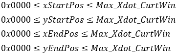
Purpose: Draw a line between the specified start and end (x, y) positions with the specified color (background or character).
Notes:
· This command only affects the currently-selected window.
· If any parameter is outside the display’s definable area, the command is cancelled and the remaining command data is treated as character code.
· If a diagonal line is drawn, parts of the line may have a width of 2or more pixels.
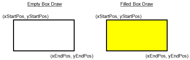
2.5.3 Draw Box
Command Code: [0x1F, 0x28, 0x64, 0x11, mode, pen,xStartPosL, xStartPosH, yStartPosL,yStartPosH, xEndPosL, xEndPosH, yEndPosL, yEndPosH]
Parameters:
| mode | Desired drawing mode. |
| pen | Set drawing color to background or character color. |
| xStartPos[xStartPosH:xStartPosL] | X position to start line. |
| yStartPos[yStartPosH:yStartPosL] | Y position to start line. |
| xEndPos[xEndPosH:xEndPosL] | X position to end line. |
| yEndPos[yEndPosH:yEndPosL] | Y position to end line. |
Settings:
| mode | Setting |
|---|---|
| 0x01 | Draw empty box |
| 0x02 | Draw filled box. |
| pen | Color |
|---|---|
| 0x00 | Background |
| 0x01 | Character |
Range: 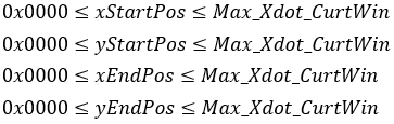
Purpose: Draw a box between the specified start and end (x, y) positions withthe specified color (background or character).
Notes:
· This command only affects the currently-selected window.
· If any parameter is outside the display’s definable area, the command is cancelled and the remaining command data is treated as character code.
2.5.4 Draw Image
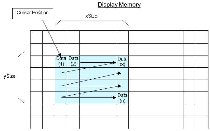
Command Code: [0x1F, 0x28, 0x66, 0x11, xSizeL, xSizeH, ySizeL, ySizeH, format,data[1]…data[n]]
Parameters:
| xSize[xSizeH:xSizeL] | Width of image in pixels. |
| ySize[ySizeH:ySizeL] | Height if image in pixels. |
| format | Image data format. |
| data | Image data. |
Settings:
| format | Type |
|---|---|
| 0x81 | 1-bit Monochrome |
| 0x86 | 6-bit Color |
| 0x8C | 12-bit Color |
| 0x90 | 16-bit Color |
| 0x98 | 24-bit Color |
| 0xF0 | BMP File |
Range: 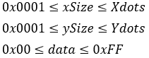
Purpose: Draw the provided image data at the current cursor position. This command does not change the cursor position.
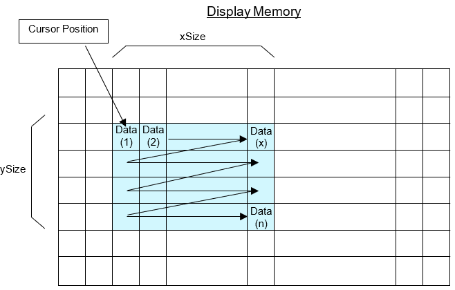
Notes:
· If the image exceeds the current window bounds, only the portion within the windows bounds will be visible.
· If the image position or size is outside the defined display area, the command is cancelled when the error is detected and the remaining data is treated as character data.
· For BMP file format, the image size specified in the file header is used.
o 1, 4, 8, 24, and 32-bit BMP files are supported.
o 16-bit BMP files are not supported.
· Refer to image data format reference for more info on data format.
2.5.5 Draw Packaged Image
Command Code: [0x1F, 0x28, 0x66, 0x21, xSizeL, xSizeH, ySizeL, ySizeH, format,data[1]…data[n]]
Parameters:
| xSize[xSizeH:xSizeL] | Width of image in pixels. |
| ySize[ySizeH:ySizeL] | Height if image in pixels. |
| format | Image data format. |
| data | Image data. |
Settings:
| format | Type |
|---|---|
| 0x86 | 6-bit Color |
| 0x8C | 12-bit Color |
| 0x98 | 24-bit Color |
Range: 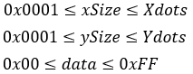
Purpose: Draw the provided image data at the current cursor position. This command does not change the cursor position.
Notes:
· If the image exceeds the current window bounds, only the portion within the windows bounds will be visible.
· If the image position or size is outside the defined display area, the command is cancelled when the error is detected and the remaining data is treated as character data.
- Refer to packaged data format reference.
2.5.6 Save RAM Image
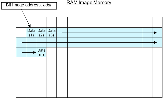
Command Code: [0x1F, 0x28, 0x66, 0x01, addrL, addrH, addrE, lengthL, lengthH, lengthE, data[1]…data[n]]
Parameters:
| addr[addrE:addrH:addrL] | Image destination address in RAM. |
| length[lengthE:length:lengthL] | Image data length. |
| data | Image data. |
Range: 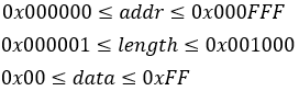
Purpose: Save image data to RAM at the specified address with the specified data length.
Notes:
· RAM image capacity is 4096 bytes.
· Images defined in RAM can be drawn on the screen using Draw Image from Memory.
· If the image address or length is outside the defined display area, the command is cancelled when the error is detected and the remaining data is treated as character data.
2.5.7 Save FROM1 Image
Command Code: [0x1F, 0x28, 0x65, 0x10, addrL, addrH, addrE, lengthL, lengthH, lengthE, data[1]…data[n]]
Parameters:
| addr[addrE:addrH:addrL] | Image destination address in FROM. |
| length[lengthE:length:lengthL] | Image data length. |
| data | Image data. |
Range: 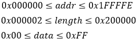
Purpose: Save image data to FROM1 at the specified address with the specified data length. Image saving is performed in chunks of 131072 bytes(128KB). For example, if a 10KB image is saved, the remaining 118KB are set to 0xFF.
Notes:
· FROM1 image capacity is 2048 bytes.
· Images defined in FROM1 can be drawn to the screen using Draw Image from Memory.
- The least significant bit for addr and length is ignored and processed as even values.
· If the image address or length is outside the defined display area, the command is cancelled when the error is detected and the remaining data is treated as character data.
· The first 2MB of FROM2 image memory overlaps with FROM1 image memory. Changing the content of this overlapping memory will affect FROM1 and2.
· An image cannot be saved if it exceeds FROM1 image capacity. If this occurs, the remaining data is treated as character data.
· To store images into FROM2 to, refer to general purpose memory store.
- This command is only value in Start User Setup Mode.
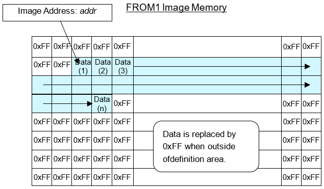
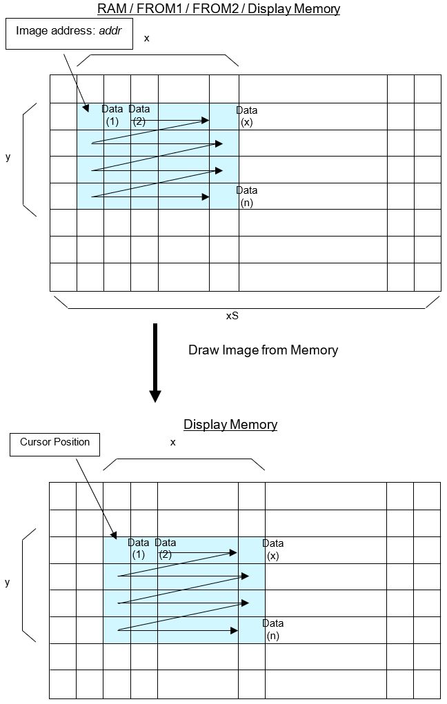
2.5.8 Draw Image from Memory
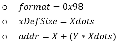
Command Code: [0x1F, 0x28, 0x66, 0x10, memory, addrL,addrH, addrE, xDefSizeL, xDefSizeH,xDispSizeL, xDispSizeH, yDispSizeL, yDispSizeH, format]
Parameters:
| memory | Memory type to draw from. |
| addr[addrE:addrH:addrL] | Saved image address. |
| xDefSize[xDefSizeH:xDefSizeL] | The saved image’s defined width. (established when image was saved) |
| xDispSize[xDispSizeH:xDispSizeL] | The image width to draw. |
| yDispSize[yDispSizeH:yDispSizeL] | The image height to draw. |
| format | Image data format. |
Settings:
| memory | Type |
|---|---|
| 0x00 | RAM |
| 0x01 | FROM1 |
| 0x02 | Display |
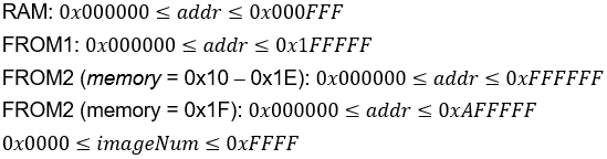
| 0x10 | FROM2 at 0x00000000 |
| 0x11 | FROM2 at 0x01000000 |
| 0x12 | FROM2 at 0x02000000 |
| 0x13 | FROM2 at 0x03000000 |
| 0x14 | FROM2 at 0x04000000 |
| 0x15 | FROM2 at 0x05000000 |
| 0x16 | FROM2 at 0x06000000 |
| 0x17 | FROM2 at 0x07000000 |
| 0x18 | FROM2 at 0x08000000 |
| 0x19 | FROM2 at 0x09000000 |
| 0x1A | FROM2 at 0x0A000000 |
| 0x1B | FROM2 at 0x0B000000 |
| 0x1C | FROM2 at 0x0C000000 |
| 0x1D | FROM2 at 0x0D000000 |
| 0x1E | FROM2 at 0x0E000000 |
| 0x1F | FROM2 at 0x0F000000 |
| format | Type |
|---|---|
| 0x81 | 1-bit Monochrome |
| 0x86 | 6-bit Color |
| 0x8C | 12-bit Color |
| 0x90 | 16-bit Color |
| 0x91 | 16-bit Color High-speed |
| 0x98 | 24-bit Color |
| 0xF0 | BMP File |
Range: 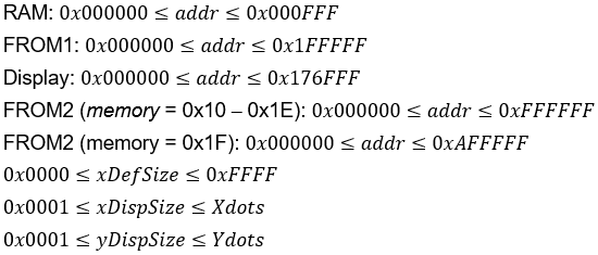
Purpose: Draw an image saved in RAM, FROM1, FROM2, or display memory at the current cursor position. The cursor position does not change after drawing is complete.
Notes:
· A portion of the saved image can be drawn on the screen. Do this by:
o Setting xDispSize lower than xDefSize
o Changing yDispSize
o Changing addr
· If the image exceeds the current window bounds, only the portion within the windows bounds will be visible.
· If the saved image data exceeds display memory while drawing, the undefined data is treated as character data.
· When memory=0x02, image data is copied from display memory. Use the following values:
§ (X, Y) are the top-left image position.
· For BMP file format, the image size specified in the file header is used.
o 1, 4, 8, 24, and 32-bit BMP files are supported.
o 16-bit BMP files are not supported.
· Display memory transfer may take longer when display orientation isat 90° and 270° than at 0° and 180°.
· FROM1 memory can be contiguously read between 0x000000 and 0x1FFFFF.(image draw can cross the 128KB block boundary)
- For 16-bit color high-speed format
o Data is transferred directly to display memory. Reverse and write mixture settings cannot be used.
o Image data must be drawn from FROM2. ( )
o The last significant bit of addr must be 0 (address must be even)
2.5.9 Draw Packaged Image from Memory
Command Code: [0x1F, 0x28, 0x66, 0x20, memory, addrL,addrH, addrE, imageNumL, imageNumH, format]
Parameters:
| memory | Memory type to draw from. |
| addr[addrE:addrH:addrL] | Saved image address. |
| imageNum[imageNumH:imageNumL] | Image number to draw. |
| format | Image data format. |
Settings:
| memory | Type |
|---|---|
| 0x00 | RAM |
| 0x01 | FROM1 |
| 0x10 | FROM2 at 0x00000000 |
| 0x11 | FROM2 at 0x01000000 |
| 0x12 | FROM2 at 0x02000000 |
| 0x13 | FROM2 at 0x03000000 |
| 0x14 | FROM2 at 0x04000000 |
| 0x15 | FROM2 at 0x05000000 |
| 0x16 | FROM2 at 0x06000000 |
| 0x17 | FROM2 at 0x07000000 |
| 0x18 | FROM2 at 0x08000000 |
| 0x19 | FROM2 at 0x09000000 |
| 0x1A | FROM2 at 0x0A000000 |
| 0x1B | FROM2 at 0x0B000000 |
| 0x1C | FROM2 at 0x0C000000 |
| 0x1D | FROM2 at 0x0D000000 |
| 0x1E | FROM2 at 0x0E000000 |
| 0x1F | FROM2 at 0x0F000000 |
| format | Type |
|---|---|
| 0x00 | Refer to image memory index. |
| 0x81 | 1-bit Monochrome |
| 0x86 | 6-bit Color |
| 0x8C | 12-bit Color |
| 0x98 | 24-bit Color |
| 0xF0 | BMP File |
Range:
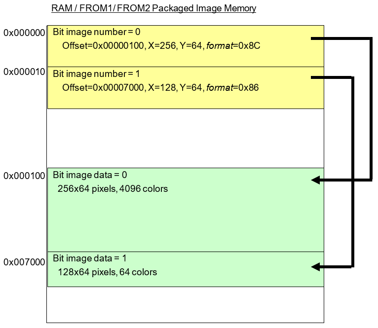
Purpose: Draw a packaged image saved in RAM, FROM1, or FROM2 at the current cursor position, specified by the image address (addr) and number ( imageNum). The cursor position does not change after drawing is complete.
Index Format for a Single Image:
|
Index Count |
Contents |
|
|
0xXXXXX0 |
Bit image data offset (offset) |
x 0x01000000 |
|
0xXXXXX1 |
x 0x010000 |
|
|
0xXXXXX2 |
x 0x0100 |
|
|
0xXXXXX3 |
x 0x01 |
|
|
0xXXXXX4 |
Reserved |
– |
|
0xXXXXX5 |
Reserved |
– |
|
0xXXXXX6 |
Pixel size X (X) |
x 0x0100 |
|
0xXXXXX7 |
x 0x01 |
|
|
0xXXXXX8 |
Pixel size Y (Y) |
x 0x0100 |
|
0xXXXXX9 |
x 0x01 |
|
|
0xXXXXXA |
format |
0x81, 0x86, 0x8C, 0x98, 0xF0 |
|
0xXXXXXB |
Reserved |
– |
|
0xXXXXXC |
Reserved |
– |
|
0xXXXXXD |
Reserved |
– |
|
0xXXXXXE |
Reserved |
– |
|
0xXXXXXF |
Reserved |
– |
Example:
Notes:
· If the image exceeds the current window bounds, only the portion within the windows bounds will be visible.
· If the saved image data exceeds display memory while drawing, the undefined data is treated as character data.
· For BMP file format, the image size specified in the file header is used.
o 1, 4, 8, 24, and 32-bit BMP files are supported.
o 16-bit BMP files are not supported.
2.6 User Window Commands
2.6.1 Select Current Window
Command Code: [0x1F, 0x28, 0x77, 0x01, window]
Parameters:
|
window |
Desired window number to select. |
Settings:
|
window |
Type |
|
0x00 |
Base-window |
|
0x01 – 0x04 |
User-window |
Range: 
Purpose: Select the current window to draw in.
Notes:
· This command is ignored if the selected window is not defined.
2.6.2 Define User Window
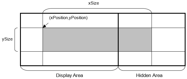
Command Code: [0x1F, 0x28, 0x77, 0x02, window, 0x01, xPositionL,xPositionH, yPositionL, yPositionH, xSizeL, xSizeH, ySizeL, ySizeH]
Parameters:
|
xPosition |
Top-left of window, x coordinate. (in pixels) |
|
yPosition |
Top-left of window, y coordinate. (in pixels) |
|
xSize |
Window width. (in pixels) |
|
ySize |
Window height. (in pixels) |
Range: 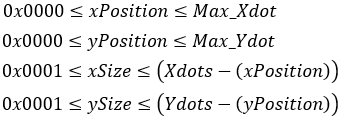
Purpose: Define a user-window’s position, width, and height in pixels. Up to 4windows can be defined. Once defined, the cursor position is initialized tothe top-left of the window. (X=0, Y=0)
Notes:
· Display contents are not changed when using this command.
2.6.3 Delete User Window
Command Code: [0x1F, 0x28, 0x77, 0x02, window, 0x00]
Parameters:
|
window |
Desired window number to delete. |
Range: 
Purpose: Delete the desired user-window. When a window is deleted, its definition iserased. Upon deletion, the base window becomes the currently-selected window.
Notes:
· Display contents are not changed when using this command.
2.7 User Setup Mode Commands
2.7.1 Start User Setup Mode
Command Code: [0x1F, 0x28, 0x65, 0x01, 0x49, 0x4E]
Purpose: Start user setup mode. Upon entering user setup mode, 4 bytes of data is transmitted and must be read before executing any commands in user setup mode. The following commands are only valid in user setup mode:
- End User Setup Mode
- Save FROM1 Image
- Save User Character
· Define FROM User Font
· Define FROM Extension User Font
- Define FROM Macro
- Delete FROM Macro
· Set Memory Switch (MSW)
Response:
|
Data |
Hex |
Data Length |
|
(1) Header |
28h |
1 byte |
|
(2) Identifier 1 |
65h |
1 byte |
|
(3) Identifier 2 |
01h |
1 byte |
|
(4) NUL |
00h |
1 byte |
Notes:
- This command is only valid in normal mode.
· The display is cleared upon entering user setup mode.
2.7.2 End User Setup Mode
Command Code: [0x1F, 0x28, 0x65, 0x02, 0x4F, 0x55, 0x54]
Purpose: Exit user setup mode. Once user setup mode is exited, software RESET is performed as described below:
1. Wait for any operations to finish.
2. Trigger MBUSY.
3. Perform software RESET.
a. Execute the Initialize Display command.
b. Re-read all memory switches and jumper settings.
c. GPIO ports are re-initialized.
d. Reset all settings (user characters, macro settings, GPIO settings. Etc.) to their “power-on” state.
Notes:
- This command is only valid in user setup mode.
2.8 GPIO Port Commands
2.8.1 Set I/O Port Direction
Command Code: [0x1F, 0x28, 0x70, 0x01, portNum, direction]
Parameters:
|
portNum |
I/O port to change. |
|
direction |
Desired port direction. · Bit value=0: Input · Bit value=1: Output |
Settings:
|
direction |
||||||||
|
portNum |
b7 |
b6 |
b5 |
b4 |
b3 |
b2 |
b1 |
b0 |
|
0x00 |
GPIO 7 |
GPIO 6 |
GPIO 5 |
GPIO 4 |
GPIO 3 |
GPIO 2 |
GPIO 1 |
GPIO 0 |
|
0x01 |
GPIO 15 |
GPIO 14 |
GPIO 13 |
GPIO 12 |
GPIO 11 |
GPIO 10 |
GPIO 9 |
GPIO 8 |
|
0x02 |
GPIO 23 |
GPIO 22 |
GPIO 21 |
GPIO 20 |
GPIO 19 |
GPIO 18 |
GPIO 17 |
GPIO 16 |
|
0x03 |
– |
– |
– |
– |
– |
– |
GPIO 25 |
GPIO 24 |
Range: 
|
direction |
||||||||
|
portNum |
b7 |
b6 |
b5 |
b4 |
b3 |
b2 |
b1 |
b0 |
|
0x00 (Port 0) |
GPIO 7 |
GPIO 6 |
GPIO 5 |
GPIO 4 |
GPIO 3 |
GPIO 2 |
GPIO 1 |
GPIO 0 |
|
0x01 (Port 1) |
GPIO 15 |
GPIO 14 |
GPIO 13 |
GPIO 12 |
GPIO 11 |
GPIO 10 |
GPIO 9 |
GPIO 8 |
|
0x02 (Port 2) |
GPIO 23 |
GPIO 22 |
GPIO 21 |
GPIO 20 |
GPIO 19 |
GPIO 18 |
GPIO 17 |
GPIO 16 |
|
0x03 (Port 3) |
– |
– |
– |
– |
– |
– |
GPIO 25 |
GPIO 24 |
Purpose: Set the input or output direction for general-purpose I/O ports.
Note:
- The I/O ports are intended for simple peripheral switches and should not be used for applications where high reliability is required.
2.8.2 Set I/O Port Output Value
Command Code[0x1F, 0x28, 0x70, 0x10, portNum, value]
Parameters:
|
portNum |
I/O port to change. |
|
value |
Output value. · Bit value=0: LOW · Bit value=1: HIGH |
Settings:
|
value |
||||||||
|
portNum |
b7 |
b6 |
b5 |
b4 |
b3 |
b2 |
b1 |
b0 |
|
0x00 (Port 0) |
GPIO 7 |
GPIO 6 |
GPIO 5 |
GPIO 4 |
GPIO 3 |
GPIO 2 |
GPIO 1 |
GPIO 0 |
|
0x01 (Port 1) |
GPIO 15 |
GPIO 14 |
GPIO 13 |
GPIO 12 |
GPIO 11 |
GPIO 10 |
GPIO 9 |
GPIO 8 |
|
0x02 (Port 2) |
GPIO 23 |
GPIO 22 |
GPIO 21 |
GPIO 20 |
GPIO 19 |
GPIO 18 |
GPIO 17 |
GPIO 16 |
|
0x03 (Port 3) |
– |
– |
– |
– |
– |
– |
GPIO 25 |
GPIO 24 |
Range: 
Purpose: Set the output level for general-purpose I/O ports.
2.8.3 Transmit I/O Port Input Value
Command Code: [0x1F, 0x28, 0x70, 0x20, portNum]
Parameters:
|
portNum |
I/O port to read. |
Settings:
|
Port Data Response Reference |
||||||||
|
portNum |
b7 |
b6 |
b5 |
b4 |
b3 |
b2 |
b1 |
b0 |
|
0x00 (Port 0) |
GPIO 7 |
GPIO 6 |
GPIO 5 |
GPIO 4 |
GPIO 3 |
GPIO 2 |
GPIO 1 |
GPIO 0 |
|
0x01 (Port 1) |
GPIO 15 |
GPIO 14 |
GPIO 13 |
GPIO 12 |
GPIO 11 |
GPIO 10 |
GPIO 9 |
GPIO 8 |
|
0x02 (Port 2) |
GPIO 23 |
GPIO 22 |
GPIO 21 |
GPIO 20 |
GPIO 19 |
GPIO 18 |
GPIO 17 |
GPIO 16 |
|
0x03 (Port 3) |
– |
– |
– |
– |
– |
– |
GPIO 25 |
GPIO 24 |
Purpose: Transmit the immediate state of a general-purpose I/O port.
Response:
|
Data |
Hex |
Data Length |
|
(1) Header |
28h |
1 byte |
|
(2) Identifier (1) |
70h |
1 byte |
|
(3) Identifier (2) |
20h |
1 byte |
|
(4) Port Data |
00h-FFh |
1 byte |
Notes:
· Response time depends on the state of the receive buffer.
2.9 Macro Commands
2.9.1 Define RAM Macro
Command Code: [0x1F, 0x3A, lengthL, lengthH, data[0]…data[n]]
Parameters:
|
length[lengthH:lengthL] |
Length of RAM macro data. |
|
data[data[0]…data[n]] |
RAM macro data. |
Range: 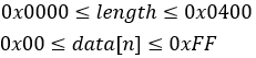
Purpose: Define a RAM macro or program macro in designated system memory (RAM).
Notes:
· If the macro data length is outside the range, the command is cancelled and the remaining data is treated as character code.
· Do not use the following commands in a macro:
o Initialize Display
o Execute Macro
o RAM Macro Processing Definition
o Enter User Setup Mode
o Image or character define/save commands
o Macro execution settings
o Memory re-write mode
o General-purpose memory commands
o Refer to DS-1940-0005-xx for program macro details.
2.9.2 Delete RAM Macro
Command Code: [0x1F, 0x3A, 0x00, 0x00]
Purpose: Delete the stored RAM macro or program macro.
2.9.3 Define FROM Macro
Command Code: [0x1F, 0x28, 0x65, 0x12, regNum, lengthL,lengthH, interval, idleTime, data[0]… data[n]]
Parameters:
|
regNum |
FROM macro registration number. |
|
length[lengthH:lengthL] |
Length of FROM macro data. |
|
Interval |
Interval time between displaying characters. (does notaffect command processing speed) |
|
idleTime |
Time between looping macro executions. |
|
data[data[0]…data[n]] |
FROM macro data. |
Range: 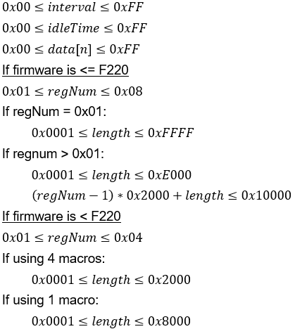
Purpose: Define an FROM macro or program macro in designated system memory (FROM).
Example:
↓No macros defined
|
FROM macro 1 area |
Undefined |
|
FROM macro 2 area |
Undefined |
|
FROM macro 3 area |
Undefined |
|
FROM macro 4 area |
Undefined |
↓Define 8KB macros in macro 1 – 4
|
FROM macro 1 area |
FROM macro 1: 8KB |
|
FROM macro 2 area |
FROM macro 2: 8KB |
|
FROM macro 3 area |
FROM macro 3: 8KB |
|
FROM macro 4 area |
FROM macro 4: 8KB |
↓Define 16KB macro in macro 2
|
FROM macro 1 area |
FROM macro 1: 8KB |
|
FROM macro 2 area |
FROM macro 2: 16KB |
|
FROM macro 3 area |
|
|
FROM macro 4 area |
FROM macro 4: 8KB |
↓Define 16KB macro in macro 3
|
FROM macro 1 area |
FROM macro 1: 8KB |
|
FROM macro 2 area |
Undefined |
|
FROM macro 3 area |
FROM macro 3: 16KB |
|
FROM macro 4 area |
↓Define 24KB macro in macro 1
|
FROM macro 1 area |
FROM macro 1: 24KB |
|
FROM macro 2 area |
|
|
FROM macro 3 area |
|
|
FROM macro 4 area |
Undefined |
Notes:
- FROM macro storage capacity
o Firmware >=F220: 64KB total, 8KB per macro (when using 8 macros)
o Firmware < F220: 32KB total, 8KB per macro (when using 4 macros)
· If a macro exceeds 8KB, multiple macro definition areas are used. This may cause other macro registration numbers to be undefined.
· If the macro data length is outside the range, the command is cancelled and the remaining data is treated as character code.
· Interval and idle Time are used when FROM macro is automatically executed on power-on.
· Do not use the following commands in a macro:
o Initialize Display
o Execute Macro
o RAM Macro Processing Definition
o Enter User Setup Mode
o Image or character define/save commands
o Macro execution settings
o Memory re-write mode
o General-purpose memory commands
o Refer to DS-1940-0005-xx for program macro details.
- This command is only valid in user setup mode.
· Data is not committed to FROM until Exit User Setup Mode
2.9.4 Delete FROM Macro
Command Code: [0x1F, 0x28, 0x65, 0x12, regNum, 0x00, 0x00]
Parameters:
|
regNum |
Desired FROM macro registration number to delete. |
Range:
 If firmware is <=F220
 If firmware is < F220
Purpose: Delete desired FROM macro or program macro from designated system memory(FROM).
Notes:
- This command is only valid in user setup mode.
2.9.5 Execute Macro
Command Code: [0x1F, 0x5E, regNum, interval, idleTime]
Parameters:
|
regNum |
FROM macro registration number. |
|
Interval |
Interval time between displaying characters. (does not affect command processing speed) |
|
idleTime |
Time between looping macro executions. |
Settings:
|
Firmware >=F220 |
|
|
regNum |
Macro Number |
|
0x00 |
RAM macro 0 |
|
0x01 – 0x08 |
FROM macro 1-8 |
|
0x80 |
RAM program macro 0 |
|
0x81 – 0x88 |
FROM program macro 1-8 |
|
Firmware < F220 |
|
|
regNum |
Macro Number |
|
0x00 |
RAM macro 0 |
|
0x01 – 0x04 |
FROM macro 1-4 |
|
0x80 |
RAM program macro 0 |
|
0x81 – 0x84 |
FROM program macro 1-4 |
Range: 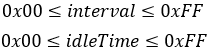
Purpose: Continuously execute the macro or program macro defined at regNum.
Notes:
· Macro execution is stopped when a command is sent to the display.
· The current window (write screen mode area of base-window) is cleared and cursor moved to home position.
· Display settings are sustained when the macro ends.
2.9.6 Set Macro End Condition
Command Code: [0x1F, 0x28, 0x69, 0x20, endCodeEnable, endCode, clearScreenEnable]
Parameters:
|
endCodeEnable |
Enable/disable macro end code. |
|
endCode |
Desired macro end code. |
|
clearScreenEnable |
Set if screen is cleared when macro ends. |
Settings:
|
endCodeEnable |
Setting |
|
0x00 |
Disable macro end code. Macro will end if data is received. |
|
0x01 |
Enable macro end code. Macro will end if the endCode byte is received.All other values are ignored. |
|
clearScreenEnable |
Setting |
|
0x00 |
Clear screen when macro ends. |
|
0x01 |
Do not clear screen when macro ends. |
Default: endCodeEnable=0x00 or MSW setting
endCode=0x00 or MSW setting
clearScreenEnable=0x00 or MSW setting
Purpose: Set the desired macro end conditions.
Notes:
- The received endCode is processed as the first byte of the next command.
· This setting is not applicable for program macro.
2.10 Memory Commands
2.10.1 Set Single Memory Switch (MSW)
Command Code: [0x1F, 0x28, 0x65, 0x03, swNum, data]
Parameters:
|
swNum |
Desired memory switch number to write to. |
|
data |
Data to write to memory switch. |
Range: 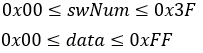
Purpose: Set the passed in value to the desired memory switch.
Notes:
- This command is only valid in Start User Setup Mode.
· Data is not saved to FROM until End User Setup Mode.
- Refer to MSW reference.
2.10.2 Set Multiple Memory Switches (MSW)
Command Code: [0x1F, 0x28, 0x65, 0x03, 0xFF, numSettings, [swNum[1], data[1]]…[swNum[numSettings], data[numSettings]]]
Parameters:
|
numSettings |
Number of memory switches to write to. |
|
swNum |
Desired memory switch number to write to. |
|
data |
Data to write to memory switch. |
Range: 
Purpose: Set passed in values to numSettings memory switches. swNum and data is sent numSettings times after numSettings in the command code sequence.
Example:
Set MSW6 to 0x01 and MSW8 to 0x02.
- numSettings=0x02
- swNum[1]=0x06
- data[1]=0x01
- swNum[2]=0x08
- data[2]=0x02
Command code sequence: [0x1F, 0x28, 0x65, 0x03, 0xFF, numSettings, swNum[1], data[1], swNum[2], data[2]]
Notes:
- This command is only valid in Start User Setup Mode.
· Data is not saved to FROM until End User Setup Mode.
- Refer to MSW reference.
2.10.3 Transmit Single Memory Switch Data (MSW)
Command Code: [0x1F, 0x28, 0x65, 0x04, swNum]
Parameters:
|
swNum |
Desired memory switch number to read from. |
Range: 
Purpose: Transmit the current value of a single memory switch.
Response:
|
Data |
Hex |
Data Length |
|
(1) Header |
0x28 |
1 byte |
|
(2) Identifier 1 |
0x65 |
1 byte |
|
(3) Identifier 2 |
0x04 |
1 byte |
|
(4) Data |
0x00-0xFF |
1 byte |
Notes:
· This command is valid in Start User Setup Mode and normal mode.
- Refer to MSW reference.
2.10.4 Transmit Multiple Memory Switch Data (MSW)
Command Code: [0x1F, 0x28, 0x65, 0x04, 0xFF, numSwitches, swNum[1] …swNum[numSwitches]]
Parameters:
|
numSwitches |
Number of memory switches to read. |
|
swNum |
Desired memory switch number to read from. |
Range: 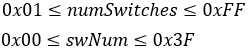
Purpose: Transmit the current value of multiple memory switches. swNum issent numSwitches times in the command sequence.
Response:
|
Data |
Hex |
Data Length |
|
(1) Header |
0x28 |
1 byte |
|
(2) Identifier 1 |
0x65 |
1 byte |
|
(3) Identifier 2 |
0x04 |
1 byte |
|
(4) Data |
0x00-0xFF |
numSwitchesbytes |
Notes:
· This command is valid in Start User Setup Mode and normal mode.
- Refer to MSW reference.
2.10.5 Write Data to General-Purpose FROM2
Command Code: [0x1F, 0x28, 0x65, 0x18, sizeL, sizeH, sizeE, memory, addrL, addrH, addrE,data[1]…data[size]]
Parameters:
|
size[sizeE:sizeH:sizeL] |
Size of data to write to FROM2. |
|
memory |
Desired memory to write to. |
|
addr[addrE:addrH:addrL] |
Address to write data to in FROM2. |
|
data |
Data to write to FROM2. |
Settings:
|
memory |
Setting |
|
0x10 |
General-Purpose FROM2 | 0x00000000 |
|
0x11 |
General-Purpose FROM2 | 0x01000000 |
|
0x12 |
General-Purpose FROM2 | 0x02000000 |
|
0x13 |
General-Purpose FROM2 | 0x03000000 |
|
0x14 |
General-Purpose FROM2 | 0x04000000 |
|
0x15 |
General-Purpose FROM2 | 0x05000000 |
|
0x16 |
General-Purpose FROM2 | 0x06000000 |
|
0x17 |
General-Purpose FROM2 | 0x07000000 |
|
0x18 |
General-Purpose FROM2 | 0x08000000 |
|
0x19 |
General-Purpose FROM2 | 0x09000000 |
|
0x1A |
General-Purpose FROM2 | 0x0A000000 |
|
0x1B |
General-Purpose FROM2 | 0x0B000000 |
|
0x1C |
General-Purpose FROM2 | 0x0C000000 |
|
0x1D |
General-Purpose FROM2 | 0x0D000000 |
|
0x1E |
General-Purpose FROM2 | 0x0E000000 |
|
0x1F |
General-Purpose FROM2 | 0x0F000000 |
|
0x30 |
General-Purpose RAM |
|
0x31 |
General-Purpose FROM |
Range:
General-Purpose FROM2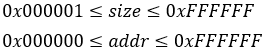
General-Purpose RAM
General-Purpose FROM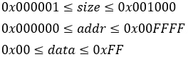
Purpose: Write the provided data into general-purpose memory. (RAM/FROM/FROM2)
Notes:
- General-purpose FROM2 valid area is 0x00000000 – 0x0FAFFFFF. (257024KB)
- General-purpose FROM is in units of 0x1000 with a total of 16areas.
· Written data can be read using Transmit General-Purpose Memory or via program macro.
· Image data stored in FROM2 can be drawn on the screen using Draw Image from Memory and Draw Packaged Image from Memory.
· When data is written to general-purpose FROM2, all other memory locations in the same 128KB block are set to 0xFF.
· When data is written to general-purpose FROM, all other memory locations in the same FROM block are set to 0xFF.
· When data is written to general-purpose RAM, data is written in the specified address range.
· General-purpose FROM2 at address 0x0E000000 is reserved for built-in outline fonts. Therefore, writes to this area are not processed.
o To write to this area, set memory to 0x1E and size to0x000000.
· This command is valid in Start User Setup Mode and normal mode.
2.10.6 Transfer General-Purpose Memory
Command Code: [0x1F, 0x28, 0x65, 0x19, sizeL, sizeH, sizeE, destMemory, destAddrL,destAddrH, destAddrE, srcMemory, srcAddrL, srcAddrH, srcAddrE]
Parameters:
|
size[sizeE:sizeH:sizeL] |
Size of data to transfer. |
|
destMemory |
Destination memory to transfer to. |
|
destAddr[destAddrE:destAddrH:destAddrL] |
Destination memory address. |
|
srcMemory |
Source memory to transfer from. |
|
srcAddr[srcAddrE:srcAddrH:srcAddrL] |
Source memory address. |
Settings:
|
destMemory,srcMemory |
Setting |
|
0x10 |
General-Purpose FROM2 | 0x00000000 |
|
0x11 |
General-Purpose FROM2 | 0x01000000 |
|
0x12 |
General-Purpose FROM2 | 0x02000000 |
|
0x13 |
General-Purpose FROM2 | 0x03000000 |
|
0x14 |
General-Purpose FROM2 | 0x04000000 |
|
0x15 |
General-Purpose FROM2 | 0x05000000 |
|
0x16 |
General-Purpose FROM2 | 0x06000000 |
|
0x17 |
General-Purpose FROM2 | 0x07000000 |
|
0x18 |
General-Purpose FROM2 | 0x08000000 |
|
0x19 |
General-Purpose FROM2 | 0x09000000 |
|
0x1A |
General-Purpose FROM2 | 0x0A000000 |
|
0x1B |
General-Purpose FROM2 | 0x0B000000 |
|
0x1C |
General-Purpose FROM2 | 0x0C000000 |
|
0x1D |
General-Purpose FROM2 | 0x0D000000 |
|
0x1E |
General-Purpose FROM2 | 0x0E000000 |
|
0x1F |
General-Purpose FROM2 | 0x0F000000 |
|
0x30 |
General-Purpose RAM |
|
0x31 |
General-Purpose FROM |
Range:
General-Purpose FROM2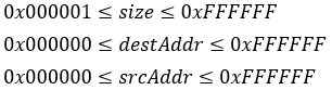
General-Purpose RAM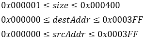
General-Purpose FROM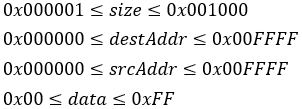
Purpose: Transfer data between general-purpose memory areas.
Notes:
- General-purpose FROM2 valid area is 0x00000000 – 0x0FAFFFFF. (257024KB)
- General-purpose FROM is in units of 0x1000 with a total of 16areas.
· When data is transferred to general-purpose FROM2, all other memory locations in the same 128KB block are set to 0xFF.
· When data is transferred to general-purpose FROM, all other memory locations in the same FROM block are set to 0xFF.
· When data is transferred to general-purpose RAM, data is written in the specified address range.
· General-purpose FROM2 at address 0x0E000000 is reserved for built-in outline fonts. Therefore, writes to this area are not processed.
· This command is valid in both Start User Setup Mode and normal mode.
- If size=0x000000, no data is transferred.
2.10.7 Transmit General-Purpose Memory
Command Code: [0x1F, 0x28, 0x65, 0x28, sizeL, sizeH, sizeE, memory, addrL, addrH, addrE]
|
size[sizeE:sizeH:sizeL] |
Size of data to transmit. |
|
memory |
Destination memory to transmit. |
|
addr[addrE:addrH:addrL] |
Destination memory address to transmit. |
Settings:
|
destMemory,srcMemory |
Setting |
|
0x10 |
General-Purpose FROM2 | 0x00000000 |
|
0x11 |
General-Purpose FROM2 | 0x01000000 |
|
0x12 |
General-Purpose FROM2 | 0x02000000 |
|
0x13 |
General-Purpose FROM2 | 0x03000000 |
|
0x14 |
General-Purpose FROM2 | 0x04000000 |
|
0x15 |
General-Purpose FROM2 | 0x05000000 |
|
0x16 |
General-Purpose FROM2 | 0x06000000 |
|
0x17 |
General-Purpose FROM2 | 0x07000000 |
|
0x18 |
General-Purpose FROM2 | 0x08000000 |
|
0x19 |
General-Purpose FROM2 | 0x09000000 |
|
0x1A |
General-Purpose FROM2 | 0x0A000000 |
|
0x1B |
General-Purpose FROM2 | 0x0B000000 |
|
0x1C |
General-Purpose FROM2 | 0x0C000000 |
|
0x1D |
General-Purpose FROM2 | 0x0D000000 |
|
0x1E |
General-Purpose FROM2 | 0x0E000000 |
|
0x1F |
General-Purpose FROM2 | 0x0F000000 |
|
0x30 |
General-Purpose RAM |
|
0x31 |
General-Purpose FROM |
Range:
General-Purpose FROM2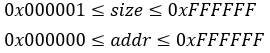
General-Purpose RAM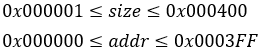
General-Purpose FROM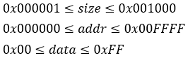
Purpose: Transmit data stored in general-purpose memory from the designated addr.
Response:
|
Data |
Hex |
Data Length |
|
(1) Header |
0x28 |
1 byte |
|
(2) Identifier 1 |
0x65 |
1 byte |
|
(3) Identifier 2 |
0x28 |
1 byte |
|
(4) Data |
0x00-0xFF |
sizebyte(s) |
Notes:
- General-purpose FROM2 valid area is 0x00000000 – 0x0FAFFFFF. (257024KB)
- General-purpose FROM is in units of 0x1000 with a total of 16areas.
· Data will not be transmitted if the address range is exceeded.
· This command is valid in both Start User Setup Mode and normal mode.
2.11 Touch Commands
2.11.1 Set Single Touch Mode
Command Code: [0x1F, 0x50, 0x01, 0x00]
Purpose: Set the desired touch mode to single touch mode. Only one simultaneous touch is reported from the module.
Notes:
· Touch data is transmitted repeatedly when the touch panel is touched.
2.11.2 Set Multi Touch Mode
Command Code: [0x1F, 0x50, 0x01, mode]
Parameters:
|
mode |
Desired touch mode. |
Settings:
|
mode |
Setting |
|
0x01 – 0x0A |
Multi-touch mode (mode=maximum simultaneous touches |
Default: mode=0x00 (See Set Single Touch Mode)
Purpose: Set the desired touch mode to multi touch mode. mode also determines the number of reported simultaneous touches during operation.
Notes:
· Touch data is transmitted for each detected touch when:
o Panel is touched
o Panel is released
o Touch position changes (see Set Coordinate Mode)
2.11.3 Set Coordinate Mode
Command Code: [0x1F, 0x50, 0x10, channel, 0x00]
Parameters:
|
channel |
Desired touch channel to configure coordinate mode. |
Range: 
Purpose: Set the desired channel to coordinate mode. This mode transmits the (x, y)coordinates related to the current touch position.
Response:
Single touch mode:
|
Data |
Hex |
Data Length |
|
(1) Header |
10h |
1 byte |
|
(2) Identifier |
00h |
1 byte |
|
(3) Data |
00h-FFh |
4 bytes tXL: x-coordinate, lower byte tXH: x-coordinate, upper byte tYL: y-coordinate, lower byte tYH: y-coordinate, upper byte |
Multi touch mode:
|
Data |
Hex |
Data Length |
|
(1) Header |
10h |
1 byte |
|
(2) Identifier |
10h, 11h |
1 byte 10h: Released 11h: Touched |
|
(3) Touch number |
01h-0Ah |
1 byte |
|
(4) Data |
00h-FFh |
4 bytes tXL: x-coordinate, lower byte tXH: x-coordinate, upper byte tYL: y-coordinate, lower byte tYH: y-coordinate, upper byte |
2.11.4 Set Switch Matrix Mode
Command Code: [0x1F, 0x50, 0x10, channel, 0x01, numSwitchesX, clearanceX, numSwitchesY, clearanceY]
Parameters:
|
channel |
Desired touch channel to configure switch matrix mode. |
|
numSwitchesX |
Number of touch switches in the X direction. |
|
clearanceX |
Pixels of clearance between touch switches in the Xdirection. |
|
numSwitchesY |
Number of touch switches in the Y direction. |
|
clearanceY |
Pixels of clearance between touch switches in the Ydirection. |
Purpose: Set the desired channel to switch matrix mode. This mode configures a matrix of touch switches. The number of touch switches in the matrix isdetermined by numSwitchesX (nx) and numSwitchesY (ny). The size of thenon-responsive area, or clearance, between the touch switches is determinedby clearanceX (cx) and clearanceY (cy). A visual representation of a touch switch matrix can be seen below.
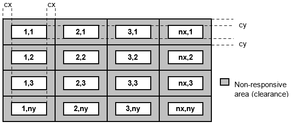
Response:
Single touch mode:
|
Data |
Hex |
Data Length |
|
(1) Header |
10h |
1 byte |
|
(2) Identifier |
01h |
1 byte |
|
(3) Data |
01h-10h |
2 bytes tX: x-direction switch number tY: y-direction switch number |
Multi touch mode:
|
Data |
Hex |
Data Length |
|
(1) Header |
10h |
1 byte |
|
(2) Identifier |
20h, 21h |
1 byte 20h: Released 21h: Touched |
|
(3) Data |
01h-10h |
2 bytes tX: x-direction switch number tY: y-direction switch number |
Notes:
· Switch button size is calculated from the supplied parameters.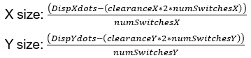
· If the calculated size is a decimal, the value is rounded down to an integer number of pixels. The remaining area forms an extra non-responsive area on the button and/or right edge of the screen.
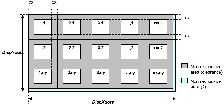
2.11.5 Set Custom Switch Mode
Command Code: [0x1F, 0x50, 0x10, channel, 0x02, numSwitches,xPosL, xPosH, yPosL, yPosH, xSizeL, xSizeH, ySizeL, ySizeH]
Parameters:
|
channel |
Desired touch channel to configure switch matrix mode. |
|
numSwitches |
Number of touch switches to define. |
|
xPos[xPosH:xPosL] |
The touch switch’s top-left X coordinate. |
|
yPos[yPosH:yPosL] |
The touch switch’s top-left Y coordinate. |
|
xSize[xSizeH:xSizeL] |
Touch switch width. |
|
ySize[ySizeH:ySizeL] |
Touch switch height. |
Range: 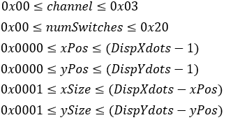
Purpose: Set the desired channel to custom switch mode. A user-defined number of touch switches are defined, each with their own position and size. Any non-defined area does not respond to touch.
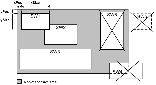
Overlapping touch switches can be defined. The lowest touch switch number is responsive in the overlapping area.
If the position (xPos, yPos) and/or size (xSize, ySize) of a touch switch is outside the display area, the corresponding touch switch number and all subsequent touch switch numbers are invalid.
Response:
Single touch mode:
|
Data |
Hex |
Data Length |
|
(1) Header |
10h |
1 byte |
|
(2) Identifier |
02h |
1 byte |
|
(3) Data |
01h-20h |
1 byte tn: Switch button number |
Multi touch mode:
|
Data |
Hex |
Data Length |
|
(1) Header |
10h |
1 byte |
|
(2) Identifier |
30h, 31h |
1 byte 30h: Released 31h: Touched |
|
(3) Data |
01h-20h |
1 bytes tn: Switch button number |
Touch data is transmitted for each switch when its touch status(touch/release) changes.
2.11.6 Set Touch Data Transmit ON
Command Code: [0x1F, 0x50, 0x20, 0x01]
Default: Touch data transmit is set to OFF.
Purpose: Turn touch data transmit ON.
Notes:
· This setting is not applicable when reading touch data within a program macro.
2.11.7 Set Touch Data Transmit OFF
Command Code: [0x1F, 0x50, 0x20, 0x00]
Purpose: Turn touch data transmit OFF. Touch data is not placed in the transmit buffer. This is the default touch transmit state.
Notes:
· This setting is not applicable when reading touch data within a program macro.
2.11.8 Set Touch Channel
Command Code: [0x1F, 0x50, 0x21, channel]
Parameters:
|
channel |
Desired touch channel. |
Range: 
Default: channel=0x00
Purpose: Set the currently active touch panel control panel. If the channel is undefined, coordinate mode is set.
2.11.9 Set Touch Threshold
Command Code: [0x1F, 0x4B 0x70, 0x00, threshold]
Parameters:
|
threshold |
Desired touch threshold value. |
Range: 
Default: MSW59 (threshold memory switch)
Purpose: Set the desired touch threshold value. Increasing the threshold value decreases touch sensitivity. Increasing the threshold value increases touch sensitivity.
Notes:
· This setting takes effect immediately, but it is stored in volatile memory.
2.11.10 Set Touch Gain
Command Code: [0x1F, 0x4B, 0x70, 0x04, gain]
Parameters:
|
gain |
Desired touch gain value. |
Range: 
Default: MSW58 (gain memory switch)
Purpose: Set the desired touch gain value. Optimum gain depends on touch sensor construction. Do not change this value.
Notes:
· This setting takes effect immediately, but it is stored in volatile memory.
2.11.11 Set Touch Standard Reference
Command Code: [0x1F, 0x4B, 0x70, 0x06, maxNoise, numMeasurements]
Parameters:
|
maxNoise |
Maximum acceptable noise value. |
|
numMeasurements |
Number of measurements to perform. |
Range: 
Purpose: Run measurement tests to verify if touch standard can be used in the current environment.
Touch standard reference is useful when sudden changes occur in the system environment for improved reliability/robustness. It also adds better reliability with thick cover glass.
This procedure must run in a controlled environment with the product in its final configuration and environment. When executed, the FLETAS touch panel is measured numMeasurements times. If the noise level measurement differences are less than maxNoise, the measurement is successful. If the difference exceeds maxNoise, then the measurement has failed. The noisiest channel’s (x, y) sensor position and noise value are transmitted.
If measurement is successful, Use Touch Standard Reference is set ON. Otherwise, Use Touch Standard Reference is set OFF.
Response:
| Data | Hex | Data Length |
|---|---|---|
| Status | 0x00 – 0x02 | 1 byte |
| 0xNN / 0xXX | 0x00 – 0xFF | 1 byte |
| 0xNX / 0xXX | 0x00 – 0xFF | 1 byte |
| 0xNY / 0xXX | 0x00 – 0xFF | 1 byte |
0x00 0xNN 0xNX 0xNY=Success (noise is within the limit)
0x01 0xNN 0xNX 0xNY=Failure (noise limit exceed)
0x02 0xXX 0xXX 0xXX=Failure (other problems / defects)
· 0xNN=Noise value of noisiest channel
· 0xNX=Noisiest channel X
· 0xNY=Noisiest channel Y
Notes:
· The resulting reference values are stored in the touch controller. However, the touch standard reference values are not saved. Upon reset, set Use Touch Standard Reference to ON to use these values again.
2.11.12 Use Touch Standard Reference
Command Code: [0x1F, 0x4B, 0x70, 0x07, 0x01]
Purpose: Use the measured touch standard reference values. This command is only valid if Set Touch Standard Reference was successful.
2.11.13 Disable Touch Standard Reference
Command Code: [0x1F, 0x4B, 0x70, 0x07, 0x00]
Purpose: Disable the use of measured touch standard reference values. This is the default state for touch standard reference use.
2.11.14 Transmit Touch Standard Reference
Command Code: [0x1F, 0x4B, 0x70, 0x08]
Purpose: Transmit the status of touch standard reference use.
Response:
| Data | Hex | Data Length |
|---|---|---|
| Status | 0x00=OFF 0x01=ON |
1 byte |
2.11.15 Save Touch Setting Package Data
Command Code: [0x1F, 0x28, 0x65, 0x1C, destination, data[1] …data[1024]]
Parameters:
|
destination |
Touch setting package data destination number. |
|
data |
Touch setting package data. |
Range: 
Purpose: Save touch setting package data to the designated destination number (1 -4).
Notes:
· Use a specific touch setting package data upon startup.
o Set MSW62 to 0x01 to use touch setting package data upon startup.
o Set MSW63 to use the associated touch setting package number upon startup.
· Contact a Noritake sales representative for standard and custom touch setting package data.
2.11.16 Set Touch Setting Package
Command Code: [0x1F, 0x4B, 0x70, 0x10, packageNum]
Parameters:
|
packageNum |
Desired package number to use. |
Range: 
Default: MSW63.
Purpose: Use the selected touch setting package number. Once this command is executed, the touch setting package settings will be in effect. The desired touch setting package data must be saved using Save Touch Setting Package Data.
2.11.17 Set Touch Scan Period for Power Save Mode
Command Code: [0x1F, 0x28, 0x61, 0x49, period]
Parameters:
|
period |
Touch scan period. |
Range: 
Default: MSW61
Purpose: Set the desired power saving mode touch scan period. Touch is scanned every period milliseconds.
Notes:
- Higher period values result in lower power consumption due to touch being scanned less times per second. However, this increases touch detection response time.
· This setting is not used if “wakeup on touch” is not set (b0=0) when using Set Power Saving Mode.