Arduino Code Library Quick Start Guide
Step 1: Download and install Arduino code library
Selecting the library for your VFD module
Determine the series by part number
- G E
1 - 2 5 6 X 6 4
2 - C –
- 7 9 3 3
3 - B
4
- 1: VFD module type
- 2: Number of dots: columns by rows
- 3: Model class
- 4: Revision note
You have a GE7000 Series OLED module if the VFD module type is “GE” and the first number of the model class is “7”.
Determine the series by part number
- G U
1 - 2 5 6 X 1 2 8
2 - C – D
- 9 0 3
3 - M
4
- 1: VFD module type
- 2: Number of dots: columns by rows
- 3: Model class
- 4: Capacitance Type
You have a GU-D Series VFD module if the VFD module type is “GU” and the first number of the model class is “9”.
Determine the series by part number
- C U
1 - 1 6 0 2
2 - 5 –
- U W 6 J
3
- 1: VFD module type
- 2: Number of characters: columns by rows
- 3: Model class
You have CU-U Series VFD module if VFD module type is “CU” and first letter of model class is “U”.
Determine the series by part number
- C U
1 - 2 4 0 4
2 - 3 –
- Y 1 A
3
- 1: VFD module type
- 2: Number of characters: columns by rows
- 3: Model class
You have CU-Y Series VFD module if VFD module type is “CU” and first letter of model class is “Y”.
Determine the series by part number
- G U
1 - 1 4 0 X 3 2
2 - F –
- 7 0 0 0
3
- 1: VFD module type
- 2: Number of dots: columns by rows
- 3: Model class
You have GU-7000 Series VFD module if VFD module type is “GU” and first number of model class is “7”.
Limitations
The library has the following known limitations:
- Analog pins: A0, A1, A2, A3, A4, A5 are not supported
- [GU-D Series] FROM image write does not function
- An Asynchronous serial interface library may not be compatible with Arduino Compatible boards
Step 2: Launch “Hello” Example
Example
|
1 2 3 4 5 6 7 8 9 10 11 12 13 14 15 16 17 18 19 20 21 22 23 24 25 26 27 28 29 30 31 32 33 34 35 36 37 38 39 40 41 42 43 44 |
#include <GE7000_Interface.h> #include <GE7000_Parallel.h> #include <GE7000_Serial_Async.h> #include <GE7000_Serial_SPI.h> #include <GE7000_Serial_Sync.h> #include <Noritake_VFD_GE7000.h> // **************************************************** // **************************************************** // Uncomment one of the communication interfaces below. // //GE7000_Serial_Async interface(38400,3, 5, 7); // BAUD RATE,SIN,BUSY,RESET //GE7000_Serial_Sync interface(3, 5, 6, 7); // SIN,BUSY,SCK,RESET //GE7000_Serial_SPI interface(3, 5, 6, 7, 8); // SIN,BUSY,SCK,RESET,CS // //Parallel interface only works on GE256X64B-7032B module //GE7000_Parallel interface('R', 8,9,10,11, 0,1,2,3,4,5,6,7); // Module Pin#3=RESET; BUSY,RESET,WR,RD,D0-D7 //GE7000_Parallel interface('B', 8,9,10,11, 0,1,2,3,4,5,6,7); // Module Pin#3=BUSY; BUSY,RESET,WR,RD,D0-D7 //GE7000_Parallel interface('N', 8,9,10,11, 0,1,2,3,4,5,6,7); // Module Pin#3=nothing; BUSY,RESET,WR,RD,D0-D7 // // **************************************************** // **************************************************** Noritake_VFD_GE7000 vfd; void setup() { _delay_ms(500); // wait for device to power up vfd.begin(256, 64); // 256x64 module // Enter the 4-digit model class number // E.g. 7040 for GU140X16G-7040A vfd.interface(interface); // select which interface to use vfd.isModelClass(7933); vfd.isGeneration('B'); // Uncomment this for B generation vfd.GE7000_reset(); // reset module vfd.GE7000_init(); // initialize module vfd.print("Hello Noritake"); // Print Hello Noritake on screen. } void loop() { } |
|
1 2 3 4 5 6 7 8 9 10 11 12 13 14 15 16 17 18 19 20 21 22 23 24 25 26 27 28 29 30 31 32 33 34 35 36 37 38 39 |
/* This code will demonstrate the different font styles of text for the display module. */ #include <GUD900_Interface.h> #include <GUD900_Serial_Async.h> #include <GUD900_Serial_SPI.h> #include <GUD900_TWI.h> #include <Noritake_VFD_GUD900.h> //Uncomment the interface that you wish to use. //GUD900_Serial_Async interface(38400, 3, 4, 5, 7); //(BAUD, OUT, IN, BUSY, RESET) //GUD900_Serial_SPI interface (3, 4, 5, 6, 7, 8); //(MOSI, MISO, BUSY, SCK, RESET, CS) //GUD900_TWI interface (0x50, 400000, 6, 7, 8); //(slaveAddress, clockFrequency, MBUSY, TRDY, RESET) Noritake_VFD_GUD900 vfd; void setup() { _delay_ms(500); vfd.begin(128, 32); vfd.interface(interface); vfd.isModelClass(903); vfd.isGeneration('S'); vfd.GUD900_reset(); vfd.GUD900_init(); // Demonstrates the difference between fixed // and proportional fonts. vfd.GUD900_setFontStyle(false, false); vfd.println("fixed: Hello Noritake"); vfd.GUD900_setFontStyle(true, false); vfd.print("proportional: Hello Noritake"); } void loop() { } |
|
1 2 3 4 5 6 7 8 9 10 11 12 13 14 15 16 17 18 19 20 21 22 23 24 25 26 27 28 29 30 31 32 33 34 35 36 37 |
#include <CUU_Interface.h> #include <CUU_Parallel_I80.h> #include <CUU_Parallel_M68.h> #include <CUU_Serial.h> #include <Noritake_VFD_CUU.h> // Uncomment one of the communication interfaces below. //CUU_Serial interface(3, 5, 6); // SIO, STB, SCK //CUU_Parallel_I80 interface(9,10,11, 0,1,2,3,4,5,6,7); //RS,RW,E,D0-D7 //CUU_Parallel_I80_4bit interface(9,10,11, 4,5,6,7); //RS,RW,E,D4-D7 //CUU_Parallel_M68 interface(9,10,11, 0,1,2,3,4,5,6,7);//RS,WR,RD,D0-D7 //CUU_Parallel_M68_4bit interface(9,10,11, 4,5,6,7);//RS,WR,RD,D4-D7 Noritake_VFD_CUU vfd; void setup() { _delay_ms(500); // wait for device to power up vfd.begin(20, 2); // 20x2 character module vfd.interface(interface); // select which interface to use // Uncomment if the target module supports brightness boost //vfd.brightnessBoost(); // module has brightness boost // Uncomment if model is DS2045G //vfd.bcVFD(); // is DS2045G vfd.CUU_init(); // initialize module //vfd.japaneseFont(); // select Japanese font for DS2045G //vfd.europeanFont(); // select European font for DS2045G vfd.print("Hello Noritake"); // print Hello Noritake on the first line } void loop() { } |
|
1 2 3 4 5 6 7 8 9 10 11 12 13 14 15 16 17 18 19 20 21 22 23 24 25 26 27 28 29 30 31 32 33 34 35 36 37 38 |
#include <CUY_Interface.h> #include <CUY_Parallel.h> #include <CUY_Serial_Async.h> #include <CUY_Serial_Sync.h> #include <Noritake_VFD_CUY.h> // **************************************************** // **************************************************** // Uncomment one of the communication interfaces below. // //CUY_Serial_Async interface(38400,3, 5, 7); // Baud rate,SIN,BUSY,RESET //CUY_Serial_Sync interface(3, 5, 6, 7); // SIN,BUSY,SCK,RESET //CUY_Parallel interface(8,9,10, 0,1,2,3,4,5,6,7); // BUSY,RESET,WR,D0-D7 // // **************************************************** // **************************************************** Noritake_VFD_CUY vfd; void setup() { _delay_ms(500); // wait for device to power up vfd.begin(20, 2); // 20x2 character module vfd.interface(interface); // select which interface to use // Enter the model class // E.g. Y1A for CU24043-Y1A // Applicable model classes: // Y1A // YX1A // Y100 // YX100 vfd.isModelClass(Y1A); vfd.CUY_init(); // initialize module vfd.print("Hello Noritake"); // print Hello Noritake on the first line } void loop() { } |
|
1 2 3 4 5 6 7 8 9 10 11 12 13 14 15 16 17 18 19 20 21 22 23 24 25 26 27 28 29 30 31 32 33 34 35 36 37 38 39 40 |
#include <GU7000_Interface.h> #include <GU7000_Parallel.h> #include <GU7000_Serial_Async.h> #include <GU7000_Serial_SPI.h> #include <GU7000_Serial_Sync.h> #include <Noritake_VFD_GU7000.h> // **************************************************** // **************************************************** // Uncomment one of the communication interfaces below. // //GU7000_Serial_Async interface(38400,3, 5, 7); // BAUD RATE,SIN,BUSY,RESET //GU7000_Serial_Sync interface(3, 5, 6, 7); // SIN,BUSY,SCK,RESET //GU7000_Serial_SPI interface(3, 5, 6, 7, 8); // SIN,BUSY,SCK,RESET,CS //GU7000_Parallel interface('R', 8,9,10,11, 0,1,2,3,4,5,6,7); // Module Pin#3=RESET; BUSY,RESET,WR,RD,D0-D7 //GU7000_Parallel interface('B', 8,9,10,11, 0,1,2,3,4,5,6,7); // Module Pin#3=BUSY; BUSY,RESET,WR,RD,D0-D7 //GU7000_Parallel interface('N', 8,9,10,11, 0,1,2,3,4,5,6,7); // Module Pin#3=nothing; BUSY,RESET,WR,RD,D0-D7 // // **************************************************** // **************************************************** Noritake_VFD_GU7000 vfd; void setup() { _delay_ms(500); // wait for device to power up vfd.begin(140, 16); // 140x16 module // Enter the 4-digit model class number // E.g. 7040 for GU140X16G-7040A vfd.isModelClass(7000); //vfd.isGeneration('B'); // Uncomment this for B generation vfd.interface(interface); // select which interface to use vfd.GU7000_reset(); // reset module vfd.GU7000_init(); // initialize module vfd.print("Hello Noritake"); // Print Hello Noritake on screen. } void loop() { } |
Step 3: Select Interface
Uncomment one of the communication interfaces below and set Arduino pins that are connected.
Code
|
1 2 3 4 5 6 7 |
//GE7000_Serial_Async interface(38400,3, 5, 7); // BAUD RATE,SIN,BUSY,RESET //GE7000_Serial_Sync interface(3, 5, 6, 7); // SIN,BUSY,SCK,RESET //GE7000_Serial_SPI interface(3, 5, 6, 7, 8); // SIN,BUSY,SCK,RESET,CS //GE7000_Parallel interface('R', 8,9,10,11, 0,1,2,3,4,5,6,7); // Module Pin#3=RESET; BUSY,RESET,WR,RD,D0-D7 //GE7000_Parallel interface('B', 8,9,10,11, 0,1,2,3,4,5,6,7); // Module Pin#3=BUSY; BUSY,RESET,WR,RD,D0-D7 //GE7000_Parallel interface('N', 8,9,10,11, 0,1,2,3,4,5,6,7); // Module Pin#3=nothing; BUSY,RESET,WR,RD,D0-D7 |
Description
-
For asynchronous serial interface uncomment:
1GE7000_Serial_Async interface(38400,3, 5, 7); // BAUD RATE,SIN,BUSY,RESET -
For synchronous serial interface uncomment:
1GE7000_Serial_Sync interface(3, 5, 6, 7); // SIN,BUSY,SCK,RESET -
For the SPI interface uncomment:
1GE7000_Serial_SPI interface(3, 5, 6, 7, 8); // SIN,BUSY,SCK,RESET,CS -
For the Parallel interface with module pin #3 set to RESET uncomment:
1GE7000_Parallel interface('R', 8,9,10,11, 0,1,2,3,4,5,6,7); // Module Pin#3=RESET; BUSY,RESET,WR,RD,D0-D7 -
For the Parallel interface with module pin #3 set to BUSY uncomment:
1GE7000_Parallel interface('B', 8,9,10,11, 0,1,2,3,4,5,6,7); // Module Pin#3=BUSY; BUSY,RESET,WR,RD,D0-D7 -
For the Parallel interface with module pin #3 unset uncomment:
1GE7000_Parallel interface('N', 8,9,10,11, 0,1,2,3,4,5,6,7); // Module Pin#3=nothing; BUSY,RESET,WR,RD,D0-D7
Syntax
- GE7000_Serial_Async interface(BAUD,SIN,BUSY,RESET)
- GE7000_Serial_Sync interface(SIN,BUSY,SCK,RESET)
- GE7000_Serial_SPI interface(MOSI,BUSY,SCK,RESET,CS)
- GE7000_Parallel interface(PIN3,BUSY,RESET,WR,RD,D0,D1,D2,D3,D4,D5,D6,D7)
Parameters
- BAUD: The desired baud rate for asynchronous serial communication.
Supported baud rates are 9600, 19200, 38400, and 115200 - SIN: The Arduino Uno pin used for the data out signal.
- BUSY: The Arduino Uno pin used for the busy signal.
- RESET: The Arduino Uno pin used for the reset signal.
- SCK: The Arduino Uno pin used for the serial clock signal.
- MOSI: The Arduino Uno pin used for the master-out-slave-in signal.
- CS: The Arduino Uno pin used for the chip select signal.
- WR: The Arduino pin connected to the write pin of the module.
- RD: The Arduino pin connected to the read pin of the module.
- PIN3: JRB jumper setting on the module. Type in ‘R’ if set to reset, ‘B’ if set to busy, and ‘N’ if unset.
- D0,D1,D2,D3,D4,D5,D6,D7: The numbers of the Arduino pins that are connected to the corresponding data pins on the VFD module
Note: The parallel interface and JRB jumper are available only applicable module.
Code
|
1 2 3 |
//GUD900_Serial_Async interface(38400, 3, 4, 5, 7); //(BAUD, OUT, IN, BUSY, RESET) //GUD900_Serial_SPI interface(3, 4, 5, 6, 7, 8); //(MOSI, MISO, BUSY, SCK, RESET, CS) //GUD900_TWI interface(0x50, 400000, 6, 7, 8); //(slaveAddress, clockFrequency, MBUSY, TRDY, RESET) |
Description
-
For asynchronous serial interface uncomment:
1GUD900_Serial_Async interface(38400, 3, 4, 5, 7); //(BAUD, OUT, IN, BUSY, RESET) -
For the SPI interface uncomment:
1//GUD900_Serial_SPI interface (3, 4, 5, 6, 7, 8); //(MOSI, MISO, BUSY, SCK, RESET, CS) -
For the TWI (I2C) interface uncomment:
1//GUD900_TWI interface (0x50, 400000, 6, 7, 8); //(slaveAddress, clockFrequency, MBUSY, TRDY, RESET)
Syntax
- GUD900_Serial_Async interface(BAUD, OUT, IN, BUSY, RESET)
- GUD900_Serial_SPI interface(MOSI, MISO, BUSY, SCK, RESET, CS)
- GUD900_TWI interface(slaveAddress, clockFrequency, MBUSY, TRDY)
Parameters
- BAUD: The desired baudrate for asynchronous serial communication.
- OUT: The Arduino Uno pin used for the data out signal.
- IN: The Arduino Uno pin used for the data in signal.
- BUSY: The Arduino Uno pin used for the busy signal.
- RESET: The Arduino Uno pin used for the reset signal.
- MOSI: The Arduino Uno pin used for the master-out-slave-in signal.
- MISO: The Arduino Uno pin used for the master-in-slave-out signal.
- SCK: The Arduino Uno pin used for the serial clock signal.
- CS: The Arduino Uno pin used for the chip select signal.
- slaveAddress: The slave address of the device. The GUD slave address is 0x50.
- clockFrequency: The desired communication clock frequency.
- MBUSY: The Arduino Uno pin used for the module busy signal.
- TRDY: The Arduino Uno pin used for the transmit-ready busy signal.
Code
|
1 2 3 4 5 |
//CUU_Serial interface(3, 5, 6); // SIO, STB, SCK //CUU_Parallel_I80 interface(9,10,11, 0,1,2,3,4,5,6,7); //RS,RW,E,D0-D7 //CUU_Parallel_I80_4bit interface(9,10,11, 4,5,6,7); //RS,RW,E,D4-D7 //CUU_Parallel_M68 interface(9,10,11, 0,1,2,3,4,5,6,7);//RS,WR,RD,D0-D7 //CUU_Parallel_M68_4bit interface(9,10,11, 4,5,6,7);//RS,WR,RD,D4-D7 |
Description
-
For synchronous serial interface (UART) uncomment:
1//CUU_Serial interface(3, 5, 7); // SIO, STB, SCK -
For parallel I80 8-bit interface uncomment:
1//CUU_Parallel_I80 interface(9,10,11, 0,1,2,3,4,5,6,7); //RS,RW,E,D0-D7 -
For parallel I80 4-bit interface uncomment:
1//CUU_Parallel_I80_4bit interface(9,10,11, 4,5,6,7); //RS,RW,E,D4-D7 -
For parallel M68 8-bit interface uncomment:
1//CUU_Parallel_M68 interface(9,10,11, 0,1,2,3,4,5,6,7);//RS,WR,RD,D0-D7 -
For parallel M68 4-bit interface uncomment:
1//CUU_Parallel_M68_4bit interface(9,10,11, 4,5,6,7);//RS,WR,RD,D4-D7
Syntax
- CUU_Serial interface(SIO,STB,SCK)
- CUU_Parallel_I80 interface(RS,RW,E,D0,D1,D2,D3,D4,D5,D6,D7)
- CUU_Parallel_I80_4bit interface(RS,RW,E,D4,D5,D6,D7)
- CUU_Parallel_M68 interface(RS,WR,RD,D0,D1,D2,D3,D4,D5,D6,D7)
- CUU_Parallel_M68_4bit interface(RS,WR,RD,D4,D5,D6,D7)
Parameters
- SIO: The number of the Arduino pins that is connected to the data pin on the VFD module
- STB: The number of the Arduino pins that is connected to strobe pin on the VFD module
- RW: The number of the Arduino pins that is connected to rw pin on the VFD module
- SCK: The number of the Arduino pins that is connected to clock pin on the VFD module
- RS: The number of the Arduino pins that is connected to rs pin on the VFD module
- E: The number of the Arduino pins that is connected to enable pin on the VFD module
- WR: The number of the Arduino pins that is connected to write pin on the VFD module
- RD: The number of the Arduino pins that is connected to read pin on the VFD module
- D0,D1,D2,D3,D4,D5,D6,D7: The numbers of the Arduino pins that are connected to the
corresponding data pins on the VFD module
Code
|
1 2 3 |
//CUY_Serial_Async interface(38400,3, 5, 7); // BAUD RATE,SIN,BUSY,RESET //CUY_Serial_Sync interface(3, 5, 6, 7); // SIN,BUSY,SCK,RESET //CUY_Parallel interface(8,9,10, 0,1,2,3,4,5,6,7); // BUSY,RESET,WR,D0-D7 |
Description
-
For asynchronous serial interface (UART) uncomment:
1//CUY_Serial_Async interface(38400,3, 5, 7); // BAUD RATE,SIN,BUSY,RESET -
For synchronous serial interface (USART) uncomment:
1//CUY_Serial_Sync interface(3, 5, 6, 7); // SIN,BUSY,SCK,RESET -
For parallel interface uncomment:
1//CUY_Parallel interface(8,9,10, 0,1,2,3,4,5,6,7); // BUSY,RESET,WR,D0-D7
Syntax
- CUY_Serial_Async interface(BAUD RATE,SIN,BUSY,RESET)
- CUY_Serial_Sync interface(SIN,BUSY,SCK,RESET)
- CUY_Parallel interface(BUSY,RESET,WR,D0,D1,D2,D3,D4,D5,D6,D7)
Parameters
- BAUD RATE: Set the baud rate for the serial communication.
Supported baud rates are 9600, 19200, 38400, and 115200 - SIN: The number of the Arduino pins that is connected to the data pin on the VFD module
- BUSY: The number of the Arduino pins that is connected to busy pin on the VFD module
- RESET: The number of the Arduino pins that is connected to reset pin on the VFD module
- SCK: The number of the Arduino pins that is connected to clock pin on the VFD module
- WR: The number of the Arduino pins that is connected to write pin on the VFD module
- D0,D1,D2,D3,D4,D5,D6,D7: The numbers of the Arduino pins that are connected to the
corresponding data pins on the VFD module
Code
|
1 2 3 4 5 6 |
//GU7000_Serial_Async interface(38400,3, 5, 7); // BAUD RATE,SIN,BUSY,RESET //GU7000_Serial_Sync interface(3, 5, 6, 7); // SIN,BUSY,SCK,RESET //GU7000_Serial_SPI interface(3, 5, 6, 7, 8); // SIN,BUSY,SCK,RESET,CS //GU7000_Parallel interface('R', 8,9,10,11, 0,1,2,3,4,5,6,7); // Module Pin#3=RESET; BUSY,RESET,WR,RD,D0-D7 //GU7000_Parallel interface('B', 8,9,10,11, 0,1,2,3,4,5,6,7); // Module Pin#3=BUSY; BUSY,RESET,WR,RD,D0-D7 //GU7000_Parallel interface('N', 8,9,10,11, 0,1,2,3,4,5,6,7); // Module Pin#3=nothing; BUSY,RESET,WR,RD,D0-D7 |
Description
-
For asynchronous serial interface (UART) uncomment:
1//GU7000_Serial_Async interface(38400,3, 5, 7); // BAUD RATE,SIN,BUSY,RESET -
For synchronous serial interface (USART) uncomment:
1//GU7000_Serial_Sync interface(3, 5, 6, 7); // SIN,BUSY,SCK,RESET -
For SPI interface uncomment:
1//GU7000_Serial_SPI interface(3, 5, 6, 7, 8); // SIN,BUSY,SCK,RESET,CS -
For parallel interface with module pin #3 set to RESET uncomment:
1//GU7000_Parallel interface('R', 8,9,10,11, 0,1,2,3,4,5,6,7); // Module Pin#3=RESET; BUSY,RESET,WR,RD,D0-D7 -
For parallel interface with module pin #3 set to BUSY uncomment:
1//GU7000_Parallel interface('B', 8,9,10,11, 0,1,2,3,4,5,6,7); // Module Pin#3=BUSY; BUSY,RESET,WR,RD,D0-D7 -
For parallel interface with module pin #3 unset uncomment:
1//GU7000_Parallel interface('N', 8,9,10,11, 0,1,2,3,4,5,6,7); // Module Pin#3=nothing; BUSY,RESET,WR,RD,D0-D7
Syntax
- GU7000_Serial_Async interface(BAUD RATE,SIN,BUSY,RESET)
- GU7000_Serial_Sync interface(SIN,BUSY,SCK,RESET)
- GU7000_Serial_SPI interface(SIN,BUSY,SCK,RESET,CS)
- GU7000_Parallel interface(PIN3,BUSY,RESET,WR,RD,D0,D1,D2,D3,D4,D5,D6,D7)
Parameters
- BAUD RATE: Set the baud rate for the serial communication.
Supported baud rates are 9600, 19200, 38400, and 115200 - SIN: The number of the Arduino pins that is connected to the data pin on the VFD module
- BUSY: The number of the Arduino pins that is connected to busy pin on the VFD module
- RESET: The number of the Arduino pins that is connected to reset pin on the VFD module
- SCK: The number of the Arduino pins that is connected to clock pin on the VFD module
- CS: The number of the Arduino pins that is connected to chip select pin on the VFD module
- PIN3: JRB Jumper setting on the VFD module. Type in “R” if set to reset, “B” if set to busy, and “N” if unset
- WR: The number of the Arduino pins that is connected to write pin on the VFD module
- RD: The number of the Arduino pins that is connected to read pin on the VFD module
- D0,D1,D2,D3,D4,D5,D6,D7: The numbers of the Arduino pins that are connected to the
corresponding data pins on the VFD module
Step 4: Configure setup()
Code
|
1 2 3 4 5 6 7 8 9 10 11 12 13 14 |
void setup() { _delay_ms(500); // wait for device to power up vfd.begin(256, 64); // 256x64 module // Enter the 4-digit model class number // E.g. 7040 for GU140X16G-7040A vfd.isModelClass(7933); vfd.interface(interface); // select which interface to use vfd.isGeneration('B'); // Uncomment this for B generation vfd.GE7000_reset(); // reset module vfd.GE7000_init(); // initialize module // Print Noritake on screen. vfd.print("Noritake"); } |
Description
-
Specify the number of characters in columns by rows:
1vfd.begin(256, 64); //256x64 dot module -
Specify the model class of the module:
1vfd.isModelClass(7933); //7933 is the model class -
Specify the generation of the module:
1vfd.isGeneration(‘B’); //B is the model class
Code
|
1 2 3 4 5 6 7 8 9 10 11 12 13 14 15 |
void setup() { _delay_ms(500); vfd.begin(128, 32); vfd.interface(interface); vfd.isModelClass(903); vfd.isGeneration('S'); vfd.GUD900_reset(); vfd.GUD900_init(); // Demonstrates the difference between fixed // and proportional fonts. vfd.GUD900_setFontStyle(false, false); vfd.println("fixed: lorem ipsum"); vfd.GUD900_setFontStyle(true, false); vfd.print("proportional: lorem ipsum"); } |
Description
-
Specify the number of characters in columns by rows:
1vfd.begin(128, 32); //128x32 dot module -
Specify the model class of the module:
1vfd.isModelClass(903); //903 is the model class -
Specify the generation of the module:
1vfd.isGeneration(‘S’); //S is the model class -
Specify the desired font style.
1vfd.GUD900_setFontStyle(false, false); //(proportional, evenSpacing) Booleans
Code
|
1 2 3 4 5 6 7 8 9 10 11 12 13 14 15 16 17 18 |
void setup() { _delay_ms(500); // wait for device to power up vfd.begin(20, 2); // 20x2 character module vfd.interface(interface); // select which interface to use // Uncomment if the target module supports brightness boost //vfd.brightnessBoost(); // module has brightness boost // Uncomment if model is DS2045G //vfd.bcVFD(); // is DS2045G vfd.CUU_init(); // initialize module //vfd.japaneseFont(); // select Japanese font for DS2045G //vfd.europeanFont(); // select European font for DS2045G vfd.print("Noritake"); // print Noritake on the first line } |
Description
-
Specify the number of characters in columns by rows:
1vfd.begin(20, 2); // 20x2 character module -
For brightness boost suppported VFD module uncomment:
1//vfd.brightnessBoost(); // module has brightness boost -
For BC-VFD VFD modules uncomment:
1//vfd.bcVFD(); // is DS2045G -
For selecting Japanese font for BC-VFD VFD modules uncomment:
1//vfd.japaneseFont(); // select Japanese font for DS2045G -
For selecting European font for BC-VFD VFD modules uncomment:
1//vfd.europeanFont(); // select European font for DS2045G
Code
|
1 2 3 4 5 6 7 8 9 10 11 12 13 14 15 |
void setup() { _delay_ms(500); // wait for device to power up vfd.begin(20, 2); // 20x2 character module vfd.interface(interface); // select which interface to use // Enter the model class // E.g. Y1A for CU24043-Y1A // Applicable model classes: // Y1A // YX1A // Y100 // YX100 vfd.isModelClass(Y1A); vfd.CUY_init(); // initialize module vfd.print("Noritake"); // print Noritake on the first line } |
Description
-
Specify the number of characters in columns by rows:
1vfd.begin(20, 2); // 20x2 character module -
Enter the model class. Applicable model classes are Y1A, YX1A, Y100, and YX100. E.g. Y1A for CU24043-Y1A:
1vfd.isModelClass(Y1A);
Code
|
1 2 3 4 5 6 7 8 9 10 11 12 13 14 15 |
void setup() { _delay_ms(500); // wait for device to power up vfd.begin(140, 16); // 140x16 module // Enter the 4-digit model class number // E.g. 7040 for GU140X16G-7040A vfd.isModelClass(7000); //vfd.isGeneration('B'); // Uncomment this for B generation vfd.interface(interface); // select which interface to use vfd.GU7000_reset(); // reset module vfd.GU7000_init(); // initialize module // Print Noritake on screen. vfd.print("Noritake"); } |
Description
-
Specify the number of dots in columns by rows:
1vfd.begin(140, 16); // 140x16 module -
Enter the 4-digit model class number. E.g. E.g. 7040 for GU140X16G-7040A:
1vfd.isModelClass(7000); -
For B generation VFD modules uncomment:
1//vfd.isGeneration('B'); // Uncomment this for B generation
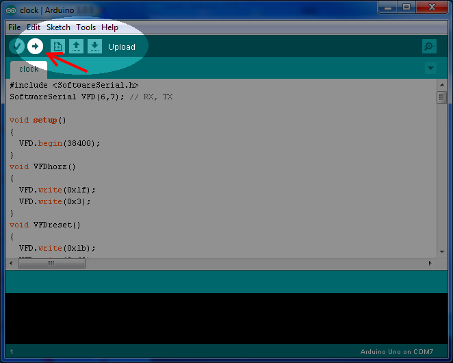
Step 5: Upload the sketch to Arduino