Display Products


Part Number Search
Compatible/Discontinued Products ListFeatured Articles
-
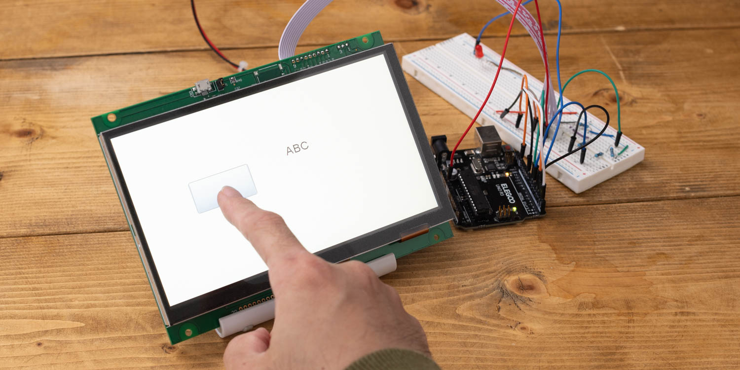
Tried Using Touch Panel TFT Display GT-SP with Arduino
In this series, as a beginner in electronics, I will be explaining the process of connecting a touch panel TFT/LCD display to Arduino and developing various things.
In this article, I used this touch screen and an Arduino to get to the point where you can touch the screen and see text on the display.Read more -
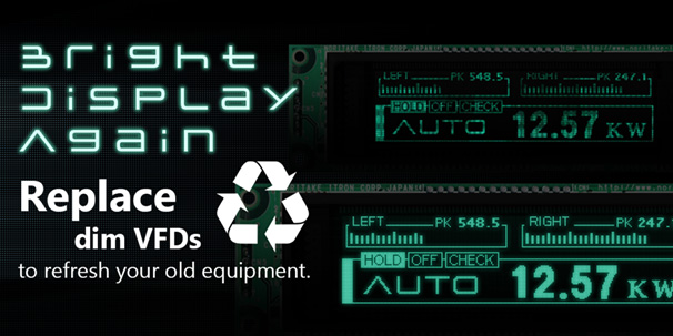
Replace dim VFDs to refresh your old equipment
Noritake VFD is pretty solid and it can display information for many years. But the VFD loses brightness over the years. During the time that a VFD is powered on, this causes the heater wire and the phosphor coating to age over time. Old equipment can be refreshed by replacing a dim VFD with a new one, providing additional years of service.Read more
-

What are Touchscreens?
What are the different types of touchscreens and how are they used? Explain about the touchscreens and Noritake's Touchscreen Technology.Read more
News / Announcements
-
Notification of change to GU112X16G-7003D/7900D, GU128X64D-7003C/7900C, GU140X16G-7000D/7003D, GU140X32F-7900D
 The following products, which were developed a long years ago and have been adopted by many customers, will no longer be produced due to the discontinuation of microcontrollers.
Therefore, we have de ...(04/15/2024)Read more
The following products, which were developed a long years ago and have been adopted by many customers, will no longer be produced due to the discontinuation of microcontrollers.
Therefore, we have de ...(04/15/2024)Read more -
Controlling a Servo Motor Connected to Arduino from a Touch Screen
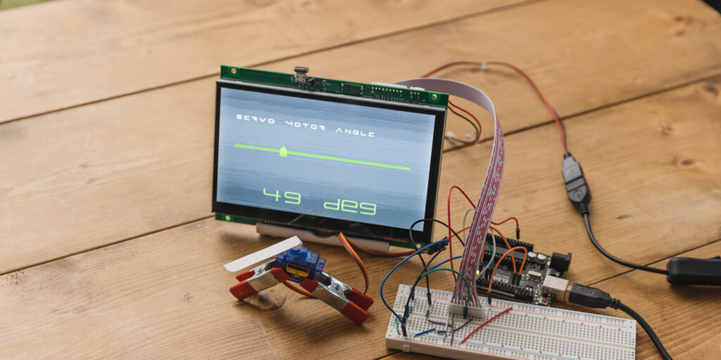 Hello everyone, I'm @kissaten, a beginner in electronics. In this series, I'm explaining the process of connecting a 7-inch touch display (GT-SP series "GTWV070S3A00P") to an Arduino and working on va ...(03/07/2024)Read more
 -
Display values obtained from Arduino in a highly visible design
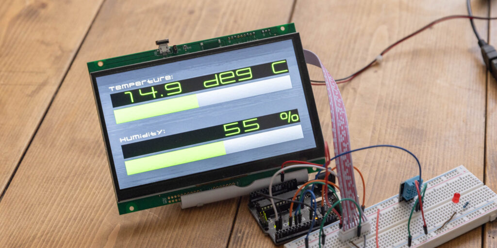 Hello everyone, I'm @kissaten, a beginner in electronics. In this series, I'm explaining the process of connecting a 7-inch touch display (GT-SP series "GTWV070S3A00P") to an Arduino and working on va ...(02/19/2024)Read more
 -
Noritake to Showcase at MD&M Anaheim Convention Center in CA
 Noritake will be at the MD&M WEST held at Anaheim Convention Center in CA. on February 6-8, 2024.
Stop by our booth (#836) lower floor to see our display products such as touch TFT/LCD and VFD.
...(12/04/2023)Read more
Noritake will be at the MD&M WEST held at Anaheim Convention Center in CA. on February 6-8, 2024.
Stop by our booth (#836) lower floor to see our display products such as touch TFT/LCD and VFD.
...(12/04/2023)Read more -
Notification of change to GU128X64D-7000C & GU140X32F-7003D
GU112X16G-7000, GU112X16G-7000B, GU112X16G-7000BL & GU140X32F-7003, GU140X32F-7003B which were developed a long years ago and have been adopted by many customers, will no longer be produced due to th ...(10/19/2023)Read more
Who is Noritake?
Noritake’s electronics division has been around since the creation of the Vacuum Fluorescent Display(VFD). We have grown to provide a wide array of products and services to ensure a smooth and efficient development cycle for your application. Our customer support staff will gladly provide you with technical support to assist with your needs.
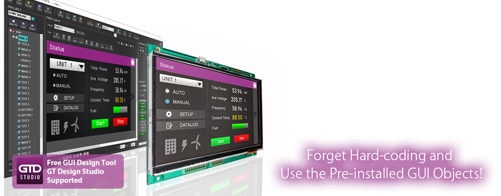
We offer an expanding set of support tools for each of our product series, including code libraries and design programs. These tools work to accelerate the evaluation and integration procedures in order to have your prototype up and running as quickly as possible.
