Series: Using the GT-SP Touch Panel TFT Display with Arduino
Display values obtained from Arduino in a highly visible design
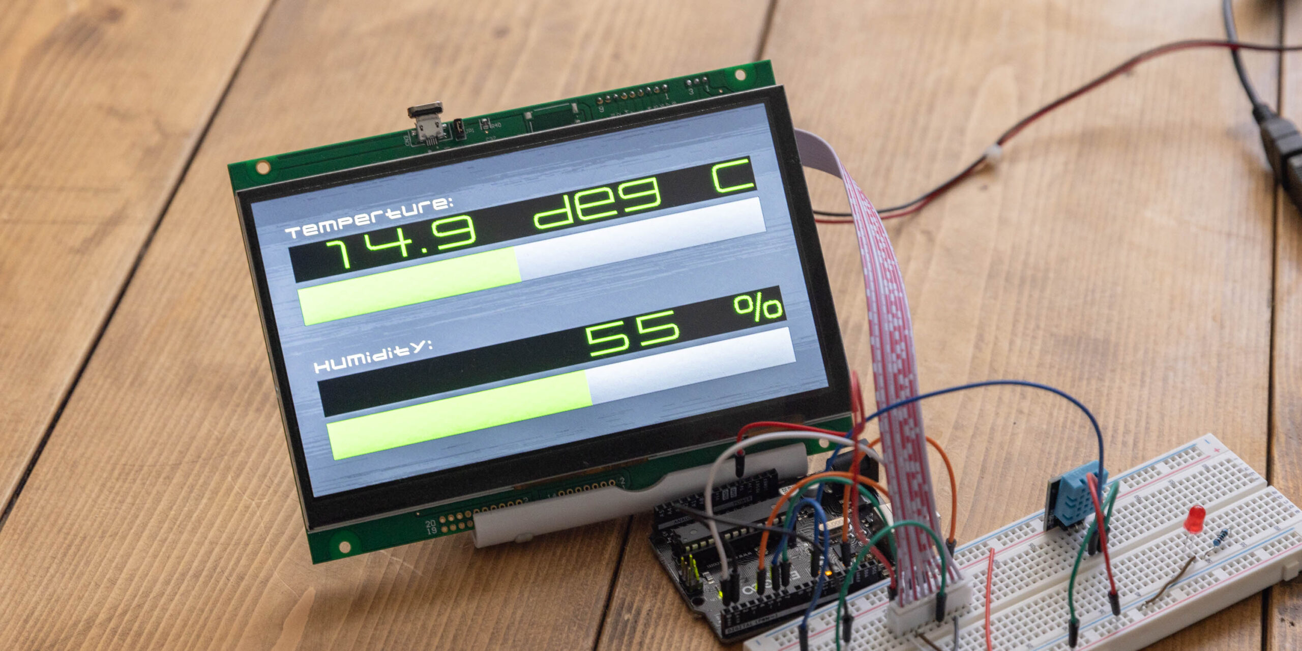
Table of Contents
DownloadDownload sample project & program (for GT Design Studio & Arduino)
Hello everyone, I’m @kissaten, a beginner in electronics. In this series, I’m explaining the process of connecting a 7-inch touch display (GT-SP series “GTWV070S3A00P”) to an Arduino and working on various projects.
Last time, we created a project that reads temperature and humidity from the DHT11 temperature and humidity sensor module and displays it on the screen. This time, I will introduce the process of adding decorations such as changing text color and bars.
Please note that this article is a continuation of the previous one (“Displaying DHT11 Sensor Module Values on Touch Screen“). If you haven’t seen the previous content yet, you can check it out here.
Decorating with GT Design Studio
This time, to decorate the sensor values, we will make some design adjustments in GT Design Studio. Specifically, we will change settings in GT-SP such as background images, font registration, and font size.
Additionally, we will also change the text color based on certain temperatures. This will be done through the Arduino program.
Object Placement
First, we place the objects. Ultimately, the image below shows the placement of text objects and bar objects.
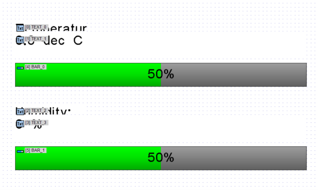
The object assignments are as follows:
- Object 0 … TEXT_0
- Object 1 … TEXT_1
- Object 2 … TEXT_2
- Object 3 … TEXT_3
- Object 4 … BAR_0
- Object 5 … BAR_1
TEXT_1 and TEXT_3 each have a default numerical value of “0.0 deg C” and “0 %” respectively.
Adding a Background Image
The background image for the page is registered in the properties.
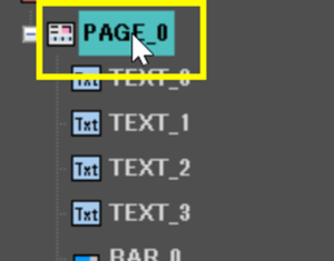
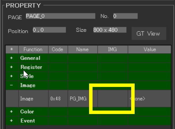
After selecting the page object “PAGE_0”, clicking the blank part of the “Image” column in the “Image” group of properties will open the image registration screen.
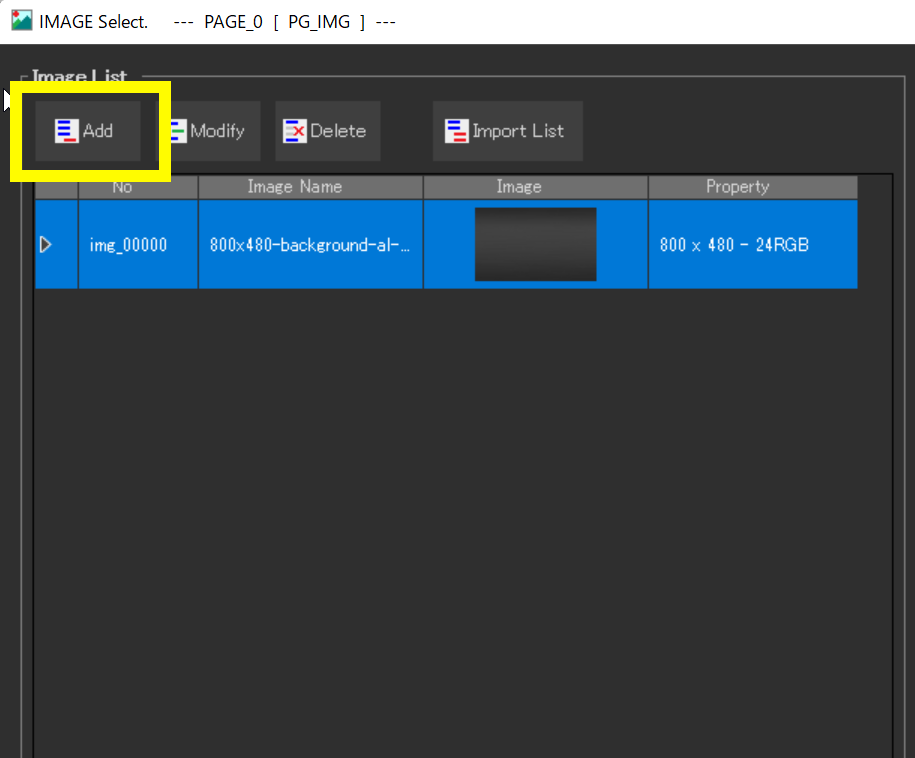
In the IMAGE Select window, you register an image using the “Add” button. This time, I registered a PNG file of size 800×480 as shown below.

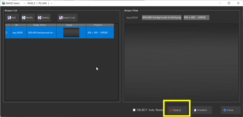
After selecting the registered image, pressing the “Select” button at the bottom right of the IMAGE Select window will display it as the page background image.
Registering User Fonts
This time, instead of the default font, I tried registering a free PC font as a user font for the various text objects.
First, prepare the font you want to register. This time, I downloaded the “Melete” font from the following site:
http://dotcolon.net/font/melete
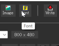
Next, from “Font” at the top of the GT Design Studio screen, display the registration screen.
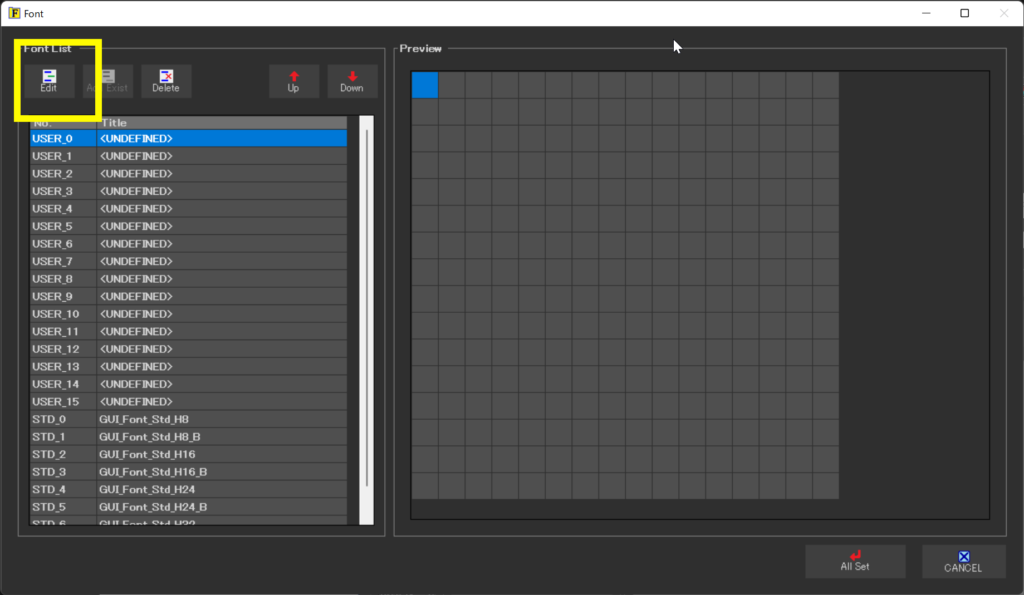
Then press “User_0” and then the “Edit” button at the top left.
In the next screen, from the Convert Setting section, select the font you want to register from the dropdown under ①Font.
Then, pressing the red inverted triangle “Convert” button ② below will convert the font and display it in the preview.
Here, change the “Height,” “Size,” and “Margin Right” until it reaches the desired size.
Finally, register the user font by pressing the ③ “Set Font Data” button at the bottom right.
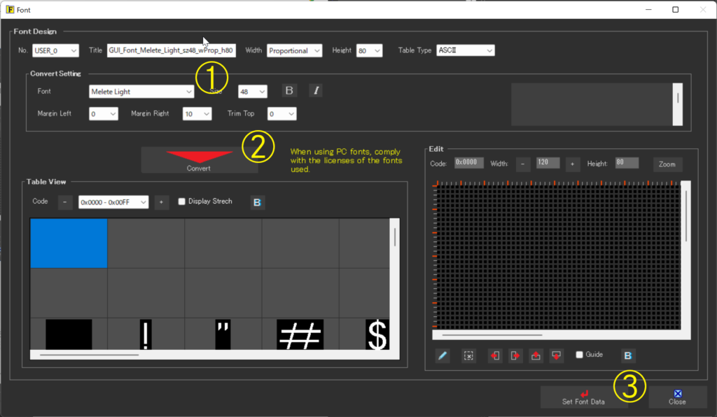
This time, I set USER_0 to the PC font “Melete Light” with a Height of “80,” Size “40,” and “Margin Right” of “10”. For USER_1, I set the PC font “Melete Medium” with a Height of “24,” Size “16,” and “Margin Right” of “5.”
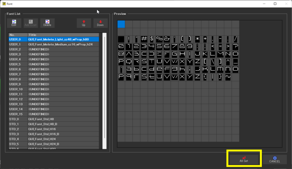
After registration, press the “All Set” button at the bottom right.
Using User Fonts
The registered fonts can be selected and used from the properties of the text object. Below is the property screen for TEXT_1.
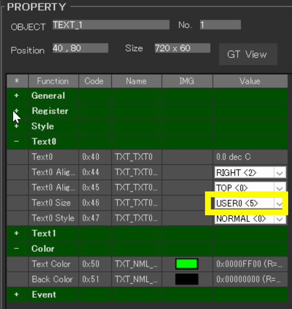
In the properties, select “Text0” > “Text 0 Size” Value and set it to “USER0<5>”. This applies the USER_0 user font we registered earlier. Since there are four text objects this time, each has been selected as follows:
- TEXT_0 —– USER1<6> (Melete Medium)
- TEXT_2 —– USER1<6> (Melete Medium)
- TEXT_1 —– USER0<5> (Melete Light)
- TEXT_3 —– USER0<5> (Melete Light)
Changing Colors
Next, we change the color of the text.
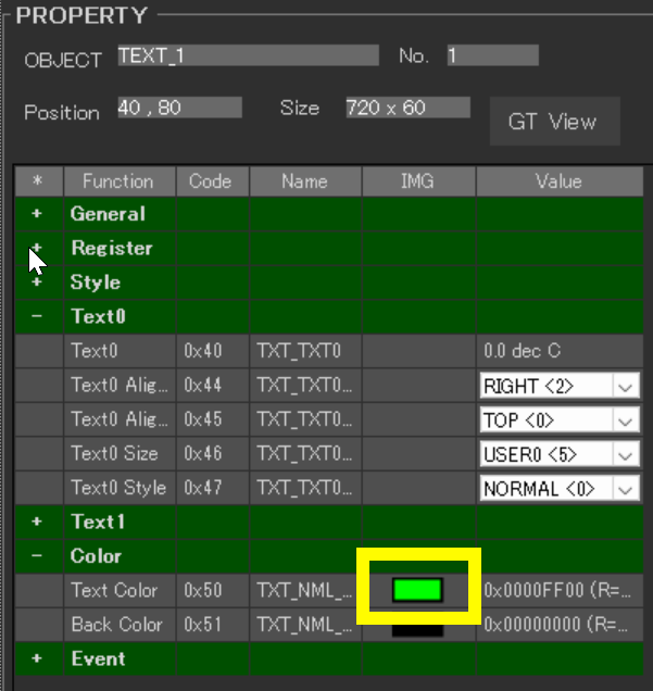
You can set this from the COLOR Select window that appears when you click the square in the IMG column of “Color” > “Text Color” (which is black by default).
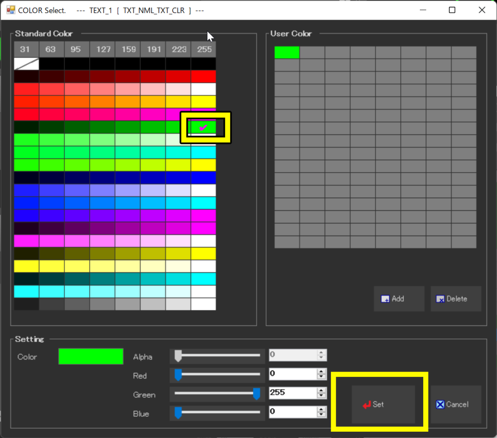
You can set the desired color by selecting it and pressing Set at the bottom right. This time, I set “green (0x0000FF00)” as the Text Color for TEXT_1 and TEXT_3. The background color is set similarly with “Back Color”.
Adjusting the Design of the Bar
We will keep the bar object’s color as default for this time.
However, the default bar displays values within it, which we want to remove.
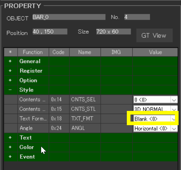
Select the bar object and set the ‘Style’ > ‘Text Format’ property to ‘Blank<0>’. This will hide the values displayed inside the bar.
Design Confirmation
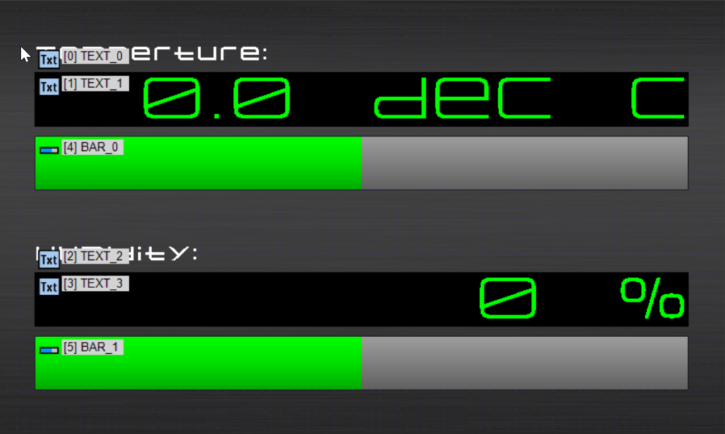
Ultimately, we achieved a preview screen like the one above.
The objects TEXT_1, TEXT_3, BAR_0, and BAR_1 serve as the recipients for the values transmitted from the Arduino, so there’s no need to set event actions for them.
Creating a Project that Writes to the Touchscreen
Following the program written in the previous article, I made the text object’s color change depending on conditions. I also made it send values to the bar object.
As a condition, if the temperature exceeds 21 degrees, the text object’s color turns red. Also, if the humidity falls below 36%, the text object’s color turns red.
Here is the program.
DownloadDownload sample project & program (for GT Design Studio & Arduino)
|
1 2 3 4 5 6 7 8 9 10 11 12 13 14 15 16 17 18 19 20 21 22 23 24 25 26 27 28 29 30 31 32 33 34 35 36 37 38 39 40 41 42 43 44 45 46 47 48 49 50 51 52 53 54 55 56 57 58 59 60 61 62 63 64 65 66 67 68 69 70 71 72 73 74 75 76 77 78 79 80 81 82 83 84 85 86 87 88 89 90 91 92 93 94 95 96 97 98 99 100 101 102 103 104 105 106 107 108 109 110 111 112 113 114 115 116 117 118 119 120 121 122 123 124 125 126 127 128 129 130 131 132 133 134 135 136 137 138 139 140 141 |
#include <string.h> // 必要なヘッダーファイルをインクルード | Include necessary header files #include "DHT.h" // DHTセンサー用のライブラリをインクルード | Include library for DHT sensor // ピン設定 | Pin assignments #define GT_DTR 4 //DTR #define GT_DSR 6 //DSR #define GT_TRDY 7 //TRDY <--未使用 | unused in this sample #define DHT_SENSOR_PIN 10 // DHTセンサーのデータピン | Data pin for DHT sensor #define DHT_SENSOR_TYPE DHT11 // 使用するDHTセンサーの型 | Type of DHT sensor being used //変数 | Variable float temperature; //温度 | Temperature float humidity; //湿度 | Humidity DHT dht(DHT_SENSOR_PIN, DHT_SENSOR_TYPE); // DHTセンサーオブジェクトを作成 | Create DHT sensor object //////////////////////////////////////////////////// // setup //////////////////////////////////////////////////// void setup() { // ピン初期設定 | Pin settings pinMode(GT_DTR, INPUT); pinMode(GT_DSR, OUTPUT); pinMode(GT_TRDY, INPUT); digitalWrite(GT_TRDY, LOW); // シリアル通信設定 | Serial communication settings Serial.begin(38400); // 38400bps Baud rate Serial.setTimeout(100); // シリアルタイムアウト | Serial timeout dht.begin(); // DHTセンサーの初期化 | Initialize DHT sensor } //////////////////////////////////////////////////// // loop //////////////////////////////////////////////////// void loop() { //温度と湿度の取得 | Get temperature and humidity temperature = dht.readTemperature(false); // trueならば華氏 それ以外は摂氏 | Fahrenheit if true, Celsius otherwise humidity = dht.readHumidity(); if (isnan(humidity) || isnan(temperature)) { // センサーからの読み取りエラー時のメッセージ出力 | Output error message for sensor read failure gtsp_ObjPrpSet_string(1, 0x40, "Error"); //Object No.1 / 0x40 = Text0 gtsp_ObjPrpSet_string(3, 0x40, "Error"); //Object No.3 / 0x40 = Text0 } else{ //温度と湿度の出力 | Output temperature and humidity gtsp_ObjPrpSet_string(1, 0x40, String(temperature,1) + " deg C"); //Object No.1 / 0x40 = Text0 gtsp_ObjPrpSet_string(3, 0x40, String(humidity,0) + " %"); //Object No.3 / 0x40 = Text0 if (temperature >= 21.0) { // 温度が21度以上の場合 | if temperature is 21 degrees Celsius or higher gtsp_ObjPrpSet_val(1, 0x50, 4, 0x00FF0000); // オブジェクト1の色を赤に設定 (例: RGBAで 0xFF0000FF = 赤) | Set object 1 color to red (e.g. 0xFF0000FF = red in RGBA) } else { // デフォルトの色を設定 | Set default color) gtsp_ObjPrpSet_val(1, 0x50, 4, 0x0000FF00); // オブジェクト1の色を緑に設定 | Set object 1 color to green } if (humidity < 36) { // 湿度が36未満場合 | If humidity is less than 36 gtsp_ObjPrpSet_val(3, 0x50, 4, 0x00FF0000); // オブジェクト3の色を赤に設定 | Set object 3 color to red } else { // デフォルトの色を設定 | Set default color) gtsp_ObjPrpSet_val(3, 0x50, 4, 0x0000FF00); // オブジェクト3の色を緑に設定 | Set object 3 color to green } int tempbar = map(temperature, 0, 30, 0, 100); // 温度を0から30度を0から100の範囲にマッピング | Mapping temperature from 0 to 30 degrees Celsius in the range 0 to 100 gtsp_ObjPrpSet_val(4, 0x10, 4, tempbar); // Object No.4 / 0x10 = Bar0 int humbar = map(humidity, 0, 100, 0, 100); // 湿度を0から100%を0から100の範囲にマッピング | Mapping humidity from 0 to 100% in the range 0 to 100 gtsp_ObjPrpSet_val(5, 0x10, 4, humbar); // Object No.5 / 0x10 = Bar1 } delay(2000); } /********************** 関数 | Function **********************/ //////////////////////////////////////////////////// // オブジェクト制御コマンド-プロパティ設定(数値用) | Object Control Command -Property Setting (for Value) // (バイト長4バイトまで | Byte length is up to 4 byte) //////////////////////////////////////////////////// void gtsp_ObjPrpSet_val(int obj, int prp, int ln, unsigned long val ) { gt_print("CMD"); //コマンドヘッダ | Command header gt_put(0xd3); //オブジェクト-プロパティ設定コマンド | Object-Property Setting gt_put(obj >> 0); //オブジェクトNo. 下位バイト | Object No. Lower byte gt_put(obj >> 8); //オブジェクトNo. 上位バイト| Object No. Upper byte gt_put(prp >> 0 ); //プロパティNo. 下位バイト | Property No. Lower byte gt_put(prp >> 8); //プロパティNo. 上位バイト| Property No. Upper byte gt_put(ln >> 0); //データ長 最下位バイト | Data length Least significant byte gt_put(ln >> 8); //データ長 下位バイト | Data length second byte gt_put(ln >> 16); //データ長 上位バイト | Data length third byte gt_put(ln >> 24); //データ長 最上位バイト| Data length Most significant byte if (ln >=1){ gt_put(val >> 0); } //データ 最下位バイト | Data Least significant byte if (ln >=2){ gt_put(val >> 8); } //データ 下位バイト | Data second byte if (ln >=3){ gt_put(val >> 16); } //データ 上位バイト | Data third byte if (ln >=4){ gt_put(val >> 24); } //データ 最上位バイト| Data Most significant byte } //////////////////////////////////////////////////// // オブジェクト制御コマンド - プロパティ設定 (文字列用) | Object Control Command -Property Setting (for String) //////////////////////////////////////////////////// void gtsp_ObjPrpSet_string(int obj, int prp, String val ) { gt_print("CMD"); //コマンドヘッダ | Command header gt_put(0xd3); //オブジェクト-プロパティ設定コマンド | Object-Property Setting gt_put(obj >> 0); //オブジェクトNo. 下位バイト | Object No. Lower byte gt_put(obj >> 8); //オブジェクトNo. 上位バイト| Object No. Upper byte gt_put(prp >> 0); //プロパティNo. 下位バイト | Property No. Lower byte gt_put(prp >> 8); //プロパティNo. 上位バイト| Property No. Upper byte gt_put(val.length() >> 0); //データ長 最下位バイト | Data length Least significant byte gt_put(val.length() >> 8); //データ長 下位バイト | Data length second byte gt_put(val.length() >> 16); //データ長 上位バイト | Data length third byte gt_put(val.length() >> 24); //データ長 最上位バイト| Data length Most significant byte gt_print(val); //文字列送信 | Send String } //////////////////////////////////////////////////// // 1byte送信 | Send byte to GT-SP //////////////////////////////////////////////////// void gt_put(unsigned char onebyte) { while ( digitalRead(GT_DTR) == HIGH ) {} //busycheck Serial.write(onebyte); } //////////////////////////////////////////////////// // 文字列送信 | Send String to GT-SP //////////////////////////////////////////////////// void gt_print(String val) { int val_i; //文字列を1文字ずつ送信 | Send string per one byte for (val_i = 0; val_i < val.length(); val_i++) { while ( digitalRead(GT_DTR) == HIGH ) {} //busycheck Serial.print(val.substring(val_i, val_i+1)); } } |
Interpreting the Program
From the last program, we added sections to change the text color based on temperature and humidity values and to send numbers to the bar object. These are the sections starting with “if (temperature >= 21.0) {” and “if (humidity < 36) {“, as well as the “int tempbar” and “int humbar” parts.
Also, we’ve added the “gtsp_ObjPrpSet_val” function this time. For example, “gtsp_ObjPrpSet_val(1, 0x50, 4, 0x00FF0000);” sends a command to change the text color property No. “0x50” for text object 1 to red color “0x00FF0000” (FF0000 in hexadecimal).
For “int tempbar = map(temperature, 0, 30, 0, 100);”, we are using the Arduino’s map function to map the temperature range from 0 to 30 degrees to a scale from 0 to 100. This determines the position of the bar.
In this case, the range is only from 0 to 30 degrees. If you need to measure a different range, you can adjust the values of 0 and 30 accordingly.
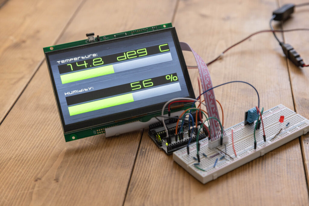
Execution Results
Although the numbers that appear are the same as in the previous article, changing the color and size of the text has increased visibility. Also, being able to actively check the increase and decrease of numbers with the bar is a good feature.
Next time, we will try a project to control a servo motor from the display.