Series: Using the GT-SP Touch Panel TFT Display with Arduino
Controlling a Servo Motor Connected to Arduino from a Touch Screen
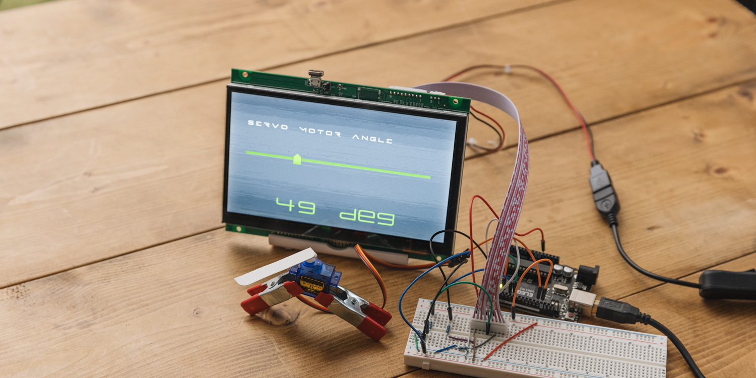
Table of Contents
DownloadDownload sample project & program (for GT Design Studio & Arduino)
Hello everyone, I’m @kissaten, a beginner in electronics. In this series, I’m explaining the process of connecting a 7-inch touch display (GT-SP series “GTWV070S3A00P”) to an Arduino and working on various projects.
In the previous session, I shared how to use GT Design Studio to transform and display data from sensors into a more visually appealing design. This time, we’re installing a decorated slider and trying to control a servo motor connected to Arduino.
To understand this article, the previous content (“Transforming values from Arduino into designs with high visibility“) serves as the foundation. We’ll be applying the object decoration techniques introduced there, so if you haven’t seen the previous article yet, please take a look.
Connecting to the Servo Motor
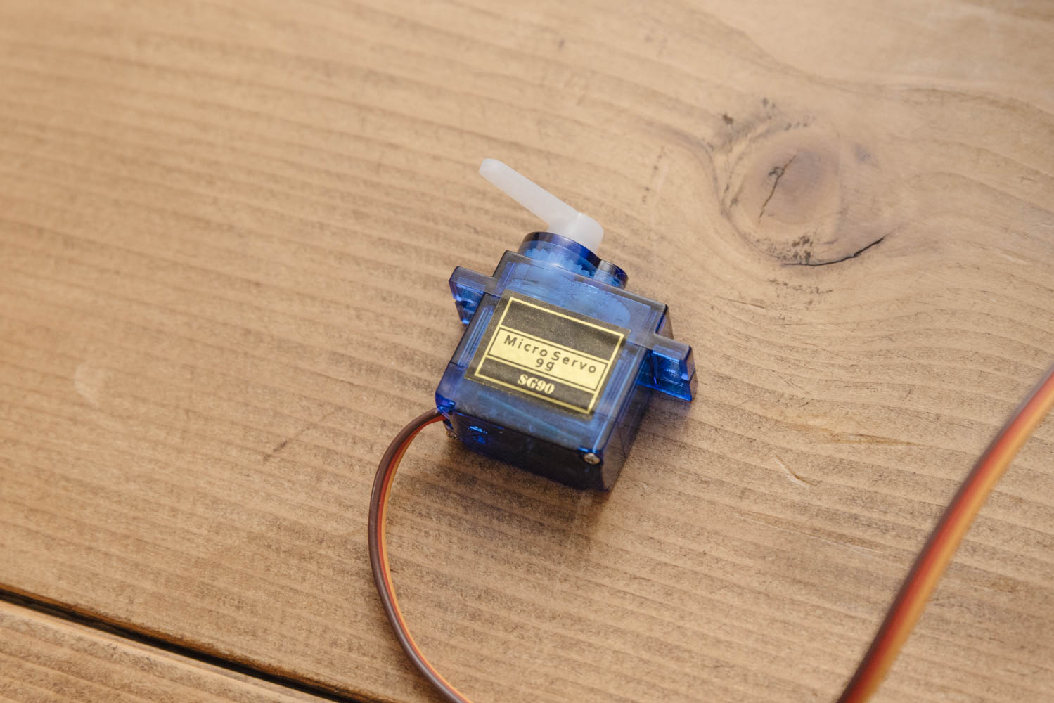
In this project, we will be using a micro servo motor model SG90. We will properly connect the servo motor’s PWM pin, the 5V power pin, and the GND pin. Specifically, the PWM pin is connected to the D13 pin of the Arduino.
The wiring between GT-SP and Arduino is omitted here. Please refer to previous articles for details if needed.
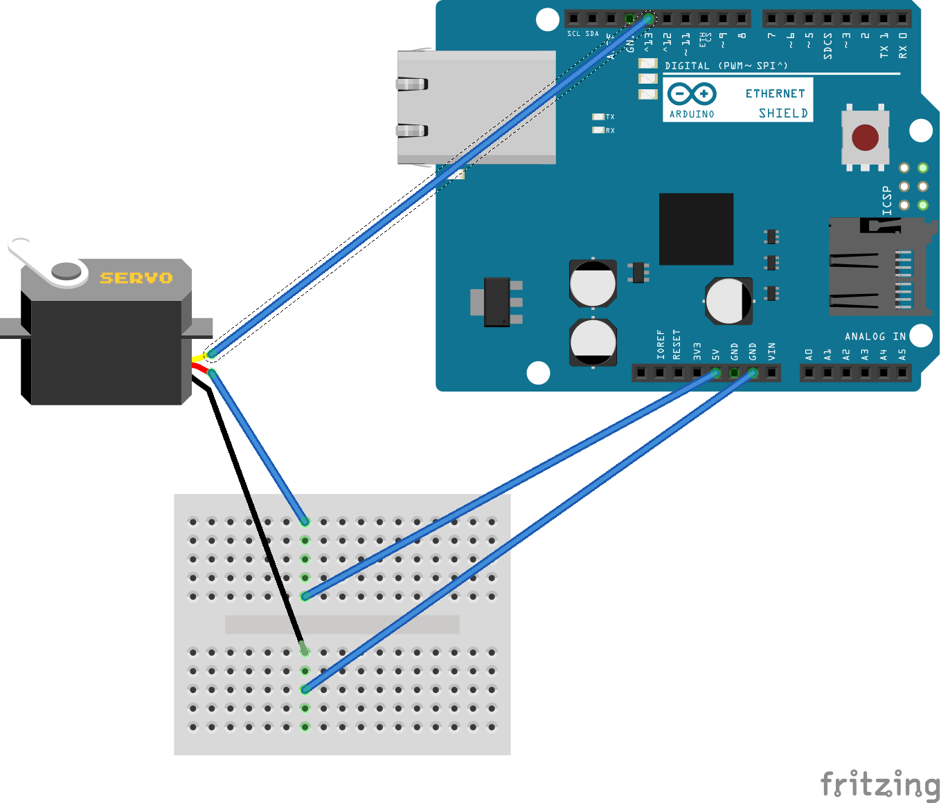
Picture by [Fritzing (CC BY-SA)]
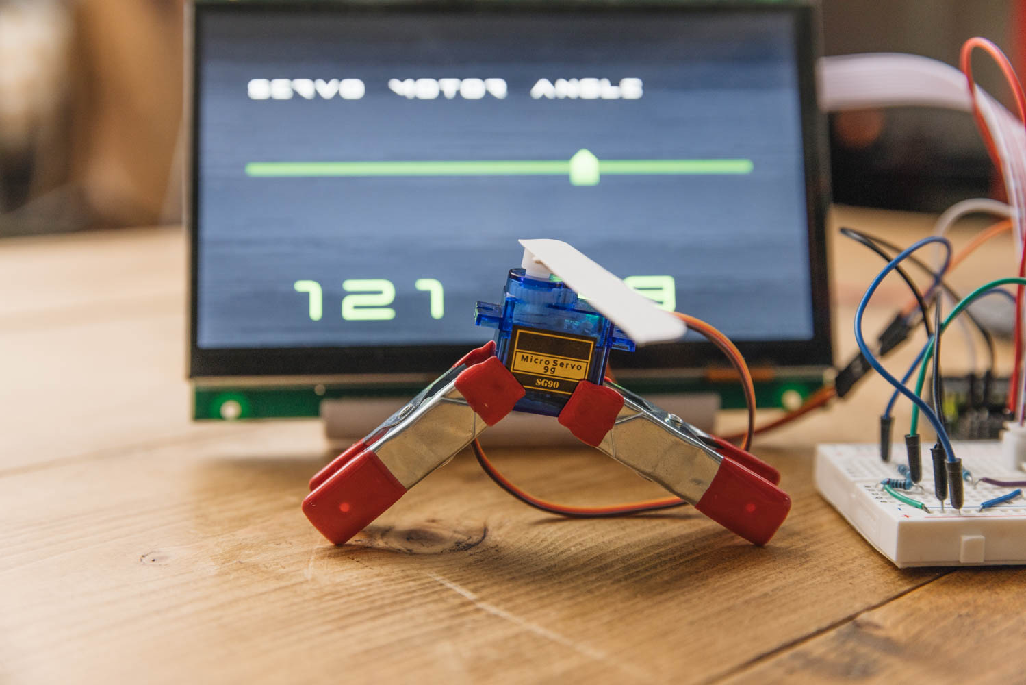
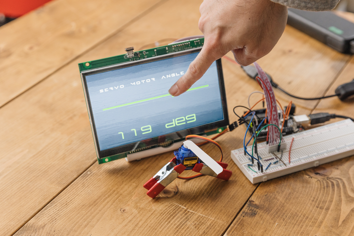
Additionally, a white stick has been attached to the servo motor to make its movements easier to see.
Decorating with GT Design Studio
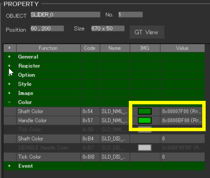
This time, we’ve adopted a slider object to control the servo motor. Sliders allow for intuitive fine-tuning, making them ideal for controlling servo motors. They help users intuitively understand parameters, facilitating precise adjustments required for servo motor control. In terms of design, we’ve made adjustments to the background, fonts, and font sizes, as well as repositioned text objects and changed the color of the slider object. This enhances both usability and visibility.
Most of the design-related procedures can be followed from the previous article. This time, we’ve specifically adjusted the alignment (Align) of the text and set the color of the slider.
Placing Objects on the Touchscreen
As the first step, we place objects that form the foundation of the project. The ultimate goal is to achieve a layout with good visibility. At this stage, text objects and slider objects are positioned appropriately. This time, we opted for a simple arrangement.
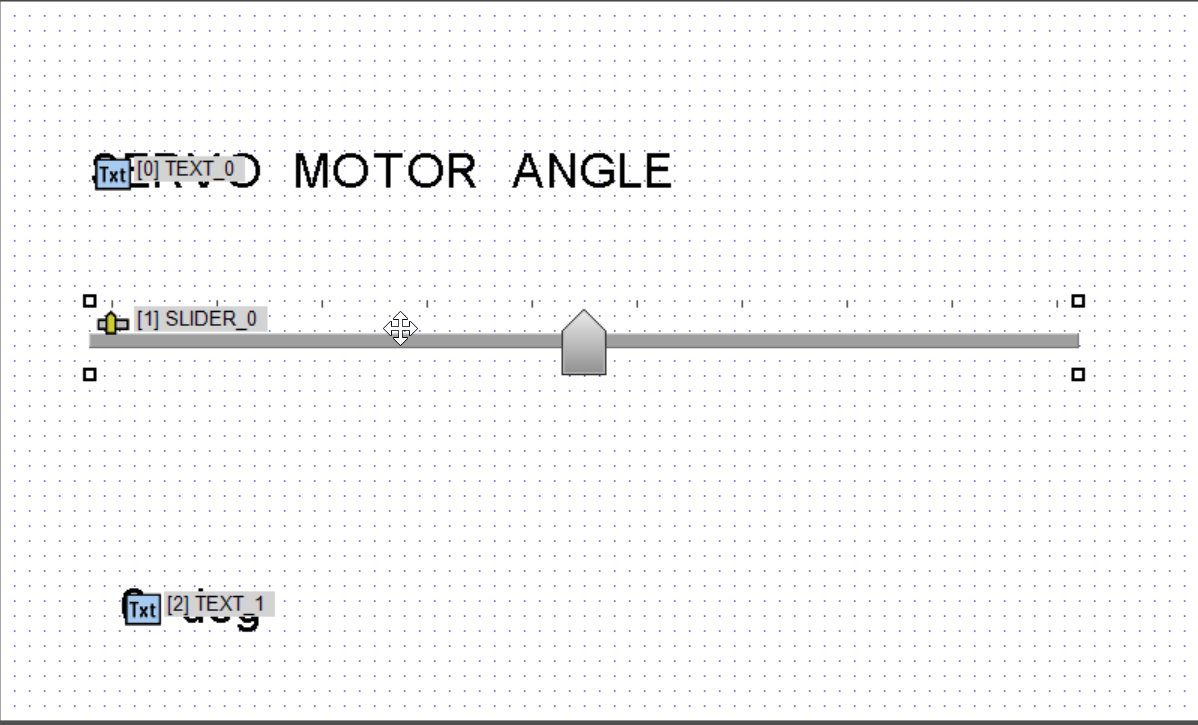
The assignment of objects is as follows:
- Object 0 … TEXT_0
- Object 1 … SLIDER_0
- Object 2 … TEXT_1
Note that the text for TEXT_1 has a default value of “0.0 deg” temporarily entered.
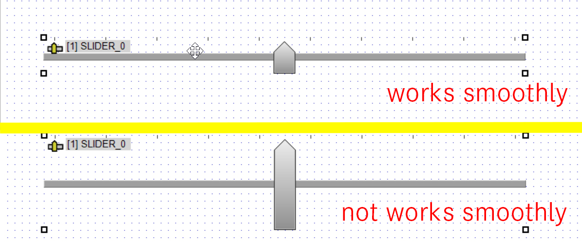
When installing slider objects, it seems that the size of the object significantly affects the system’s performance. Larger object sizes increase the load on rendering and event processing, which in turn compromises the smoothness of operation.
To address this issue, it is recommended to adjust the size of the objects appropriately and keep them to a small height as shown in the images. This will reduce the system’s load and achieve smoother operation.
This phenomenon is expected to be improved in the next update, making it possible to place larger slider objects.
Slider Event Configuration
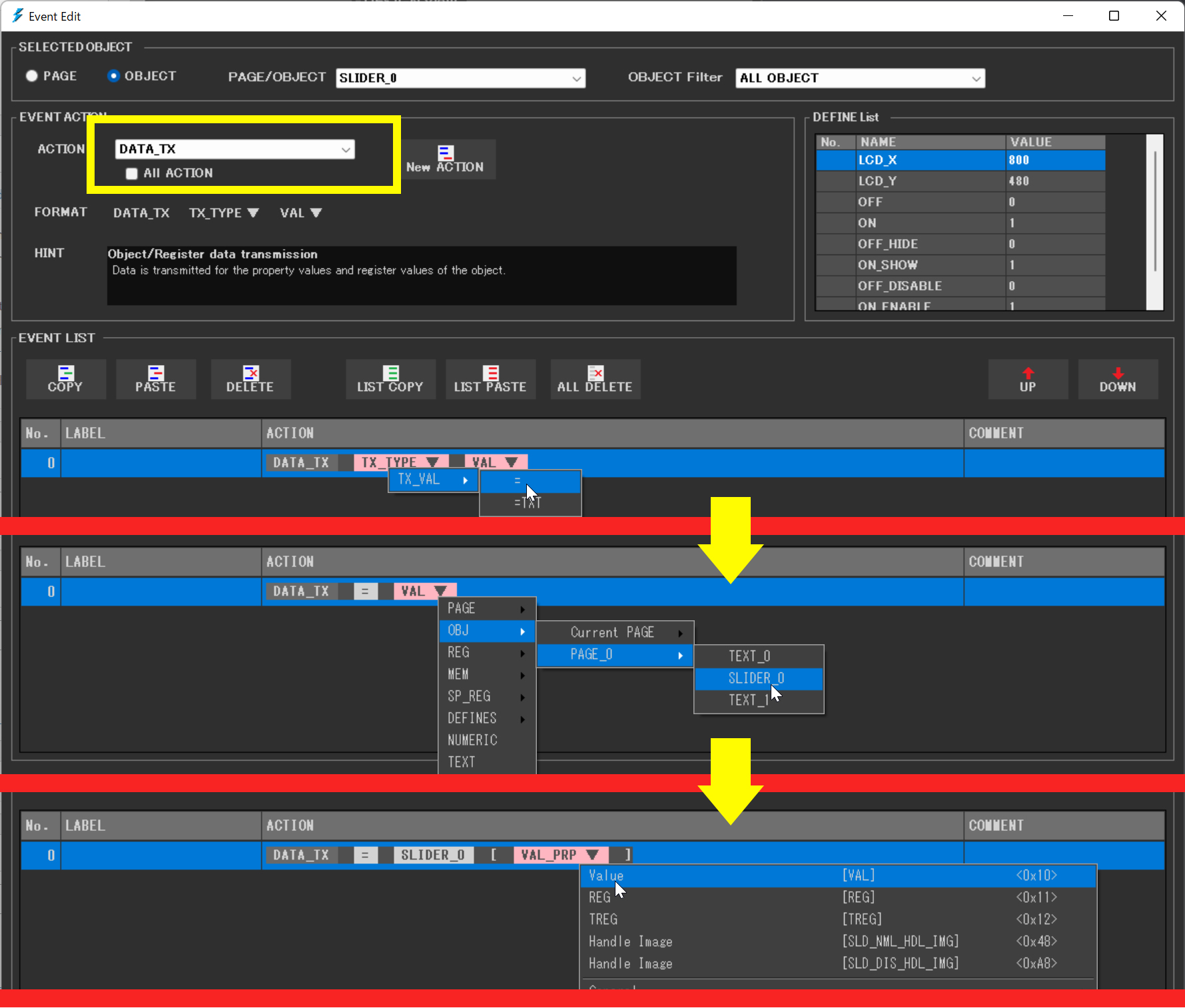
For the slider event, assign “DATA_TX” = “SLIDER_0″[VAL]. After adding “DATA_TX” from “New ACTION”, select “TX_TYPE” and choose “TX_VAL” > “=”. Next, for the “VAL” section, select “OBJ” > “PAGE_0” > “SLIDER_0”. In the newly appeared “VAL_PRP”, set it to “VAL (Value)”.
Text Decoration and Configuration
For ‘TEXT_0’, the font ‘Melete Medium’ is set with a size of 16 and line spacing of 24. On the other hand, ‘TEXT_1’ is set with the ‘Melete Light’ font, size 48, and line spacing of 80. The methods for these settings are explained in detail in the previous article, so please refer to that.
The choice of font, size, and line spacing significantly affects the visibility and readability of the design, so appropriate settings are recommended.
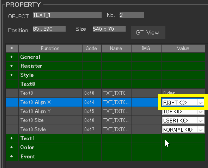
In the properties of “TEXT_1”, I selected the value for “Text0” > “Test0 Align X” and set it to “RIGHT<2>”.
Adjusting the Slider’s Maximum Value and Design
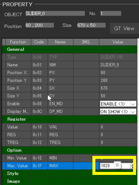
I adjusted the properties of the slider so that it outputs the value 1023 when the slider is at its farthest right position. In the properties of “SLIDER_0”, I selected the value for “Option” > “Max. Value” and set it to “1023”. This value of 1023 was chosen to utilize the full range provided by the analog input.
This setting allows for the slider’s minute changes to be accurately detected, enabling precise and fine control over the servo motor’s angle. As a result, the servo motor’s movement becomes smoother, and precise positioning is facilitated.
Verify the Design
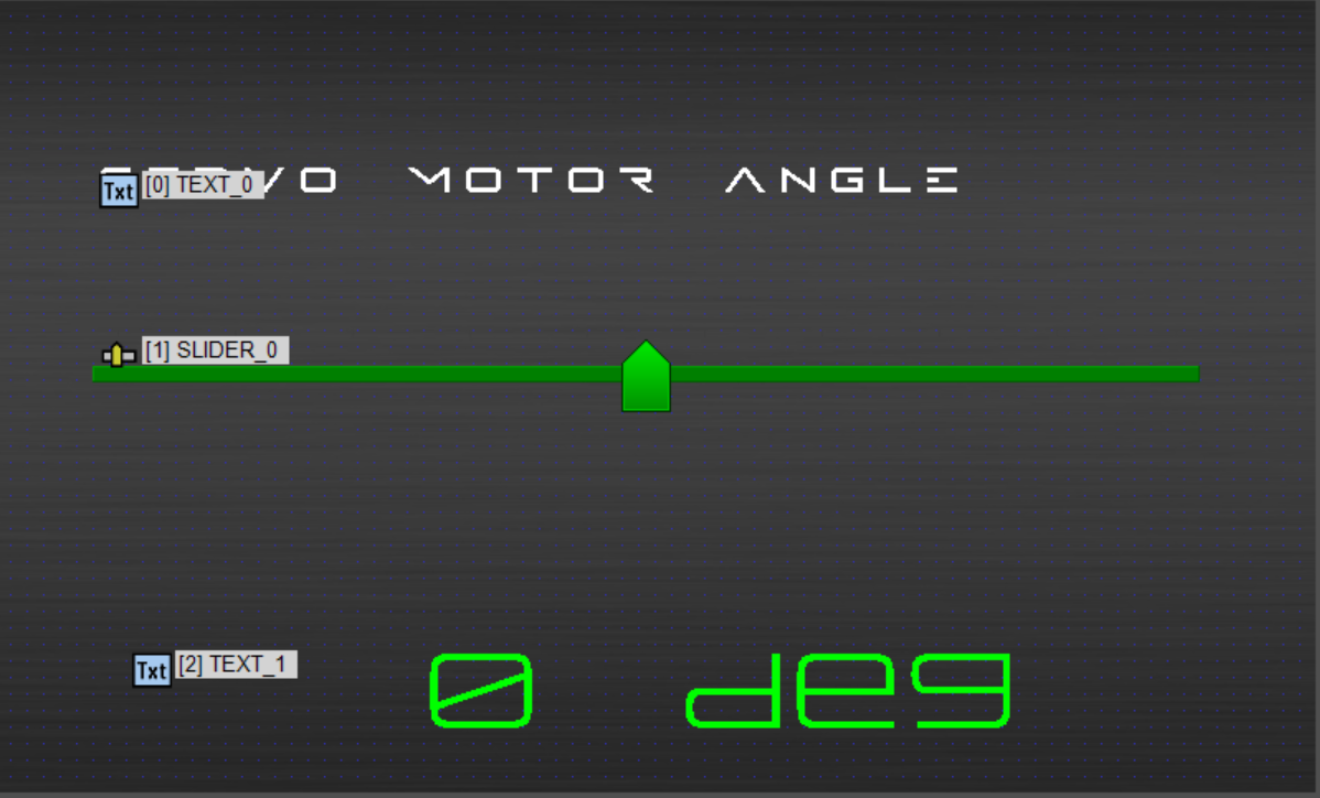
Finally, a preview screen following the above explanation has been completed. Regarding the font, we continue to use the one from the previous article.
The “TEXT_1” object functions as the receiver to display values transmitted from Arduino. Therefore, no event action settings are necessary for this object.
Creating a Project for Writing to the Touchscreen
In Arduino programming, controlling a servo motor is not particularly difficult. Arduino provides a servo motor library to facilitate easy manipulation of servo motors.
To use the servo library, you first need to include the library in your program. This can be done by adding the line #include <Servo.h> at the beginning of your program. After that, you create a servo object and attach the servo to the pin you will be using. Then, you can move the servo motor to a specific angle using the write() function.
DownloadDownload sample project & program (for GT Design Studio & Arduino)
|
1 2 3 4 5 6 7 8 9 10 11 12 13 14 15 16 17 18 19 20 21 22 23 24 25 26 27 28 29 30 31 32 33 34 35 36 37 38 39 40 41 42 43 44 45 46 47 48 49 50 51 52 53 54 55 56 57 58 59 60 61 62 63 64 65 66 67 68 69 70 71 72 73 74 75 76 77 78 79 80 81 82 83 84 85 86 87 88 89 90 91 92 93 94 95 96 97 98 99 100 101 102 103 104 105 106 107 108 109 110 111 112 113 |
#include <Servo.h> //ピン接続 | Pin assign #define GT_DTR 4 //DTR #define GT_DSR 6 //DSR #define GT_TRDY 7 //TRDY <--未使用 | unused in this sample #define RX_PIN 13 // GT-SPからのシリアルデータを受け取るピン | Pin to receive serial data from GT-SP Servo servoMotor; void setup() { //ピン初期設定 | Pin setting pinMode(GT_DTR, INPUT); pinMode(GT_DSR, OUTPUT); pinMode(GT_TRDY, INPUT); // Servoモータの初期化 | Initialization of Servo motor servoMotor.attach(RX_PIN); // シリアル通信の開始 | Sserial communication start Serial.begin(38400); //38400bps Baud rate Serial.setTimeout(100); //シリアルタイムアウト | Serial timeout } void loop() { // GT-SPデータ受信 | Receive one GT-SP response data if (Serial.available()) { // GT-SPから数値を取得 | Get values from GT-SP unsigned long gtspValue = gtsp_signal_read_numeric(); // スライダーの値を0〜180の範囲にマッピング | Mapping slider value from 0 to 180 int servoAngle = map(gtspValue, 0, 1023, 0, 180); // サーボモータを指定した角度に動かす | Move servo motor to the specified angle servoMotor.write(servoAngle); // GT-SPにサーボモータの角度を表示 | Display the angle of servo motors on GT-SP gtsp_ObjPrpSet_string(2, 0x40, String(servoAngle)+ " deg"); // シリアルモニタにサーボの角度を表示(デバッグ用)| Display the angle of the servo on the serial monitor (for debugging) Serial.print("Servo Angle: "); Serial.println(servoAngle); } } /********************** 関数 | Function **********************/ //////////////////////////////////////////////////// // データ受信(数値用) | Receive data from GT-SP (for Value) //////////////////////////////////////////////////// unsigned long gtsp_signal_read_numeric() { byte res_dl[4] = ""; unsigned long dl; if (Serial.find("RESb", 4)) { Serial.readBytes(res_dl, 4); //データ長抽出 | Read data length dl = (unsigned long)(res_dl[0] + (res_dl[1] << 8) + (res_dl[2] << 16) + (res_dl[3] << 24)); //データ長変換 | Data length // 数値を受信するためのバッファ | Buffer for receiving value byte res_data_buffer[4]; // データを読み取り | Read data Serial.readBytes(res_data_buffer, dl); // 数値に変換してリターン return (unsigned long)(res_data_buffer[0] + (res_data_buffer[1] << 8) + (res_data_buffer[2] << 16) + (res_data_buffer[3] << 24)); } // Returns 0 in case of error (needs to be modified for proper error handling) return 0; } //////////////////////////////////////////////////// // オブジェクト制御コマンド - プロパティ設定 (文字列用) | Object Control Command -Property Setting (for String) //////////////////////////////////////////////////// void gtsp_ObjPrpSet_string(int obj, int prp, String val ) { gt_print("CMD"); //コマンドヘッダ | Command header gt_put(0xd3); //オブジェクト-プロパティ設定コマンド | Object-Property Setting gt_put(obj >> 0); //オブジェクトNo. 下位バイト | Object No. Lower byte gt_put(obj >> 8); //オブジェクトNo. 上位バイト| Object No. Upper byte gt_put(prp >> 0); //プロパティNo. 下位バイト | Property No. Lower byte gt_put(prp >> 8); //プロパティNo. 上位バイト| Property No. Upper byte gt_put(val.length() >> 0); //データ長 最下位バイト | Data length Least significant byte gt_put(val.length() >> 8); //データ長 下位バイト | Data length second byte gt_put(val.length() >> 16); //データ長 上位バイト | Data length third byte gt_put(val.length() >> 24); //データ長 最上位バイト| Data length Most significant byte gt_print(val); //文字列送信 | Send String } //////////////////////////////////////////////////// // 1byte送信 | Send byte to GT-SP //////////////////////////////////////////////////// void gt_put(unsigned char onebyte) { while ( digitalRead(GT_DTR) == HIGH ) {} //busycheck Serial.write(onebyte); } //////////////////////////////////////////////////// // 文字列送信 | Send String to GT-SP //////////////////////////////////////////////////// void gt_print(String val) { int val_i; //文字列を1文字ずつ送信 | Send string per one byte for (val_i = 0; val_i < val.length(); val_i++) { while ( digitalRead(GT_DTR) == HIGH ) {} //busycheck Serial.print(val.substring(val_i, val_i+1)); } } |
Interpreting the Program
A key point in this project was the use of the mapping function to apply the maximum value of the slider set in GT Design Studio (1023) to the servo motor’s angle control.
Specifically, the following line of code converts the slider value (range from 0 to 1023) to the servo motor’s operational range (0 to 180 degrees):
int servoAngle = map(gtspValue, 0, 1023, 0, 180);
This mapping ensures a precise correlation between the slider’s position (numerical value) and the servo motor’s angle, facilitating intuitive control of the servo motor by moving the slider.
Furthermore, through serial communication, it is possible to check how the slider’s value is mapped to the servo motor’s angle, as implemented in the following lines of code:
Serial.print(“Servo Angle: “);
Serial.println(servoAngle);
While these lines are not necessary for operation, this debugging allows developers to monitor the servo motor’s movements in real-time, thereby gaining a precise understanding of the system’s behavior.
Execution Results
Setting the slider’s maximum value to 1023 and mapping that value for servo motor angle control is particularly effective in situations where fine control is required. By adopting this method, the subtle movements of the slider are directly reflected in the changes in the servo motor’s angle, enabling more delicate operations.
However, it is necessary to check whether the servo motor being used (SG90) supports control of angles to decimal places. Common servo motors like the SG90 may not be optimized for very fine angle control. Therefore, this mapping method is envisioned for use in devices or applications that can handle higher precision control.
For example, this method can be utilized in fields that require high control accuracy, such as robotics where precise positioning is demanded, or medical devices that replicate fine movements. The approach of widening the range of input values to improve the precision of the output can be applied not only to specific servo motors but also to various precision instruments.
Next time, we will take on a project that involves using various objects in GT Design Studio to alter behavior.