Series: Using the GT-SP Touch Panel TFT Display with Arduino
Setting the range of motion for a servo motor connected to an Arduino
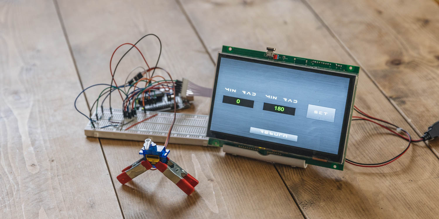
Table of Contents
DownloadDownload sample project & program (for GT Design Studio & Arduino)
Hello everyone, I’m @kissaten, a beginner in electronics. In this series, I’m explaining the process of connecting a 7-inch touch display (GT-SP series “GTWV070S3A00P”) to an Arduino and working on various projects.
In the previous episode, we used a decorated slider on the GT-SP to control a servo motor connected to the Arduino. This time, we will fine-tune the slider’s range of motion on the GT-SP using more precise controls over the objects placed on it.
Reading this article will be best understood if you are familiar with the topics discussed previously, such as “Controlling a Servo Motor Connected to Arduino from a Touch Screen” and “Display values obtained from Arduino in a highly visible design“. We will apply the decorative techniques introduced before, so if you haven’t seen the previous articles, I highly recommend checking them out.
Creating Screens in GT Design Studio
In this session, we’ll be using the servo motor featured in our previous article. As a new feature, we’ve set up a separate page and created a range of motion for the servo motor using “Edit Object”. We’ve also prepared corresponding programming.
We’ve displayed the “minimum angle” and “maximum angle” on either side of the slider and added buttons for page navigation. When moving to a page, we send the name of the destination page as a prefix. This allows the Arduino to recognize the page and perform the appropriate actions for that page.
Additionally, we’ve made it easier for the Arduino to understand what actions are being performed by prefixing operation names to strings when moving the slider or setting ranges. This prefix is sent simultaneously.
Specifically,
Page Navigation Feature:
- We’ve added a function that sends the name of the destination page when a page navigation button is pressed.
Operation Identification Feature:
- Before performing any operation, we send a string with the operation name prefixed to allow the host to identify which action is being taken.
Error Display Feature:
- We’ve added a new POPUP page to display when invalid values are entered.
For detailed designs of each feature, please refer to the previous article.
Additionally, we have set a common design for the buttons as follows.
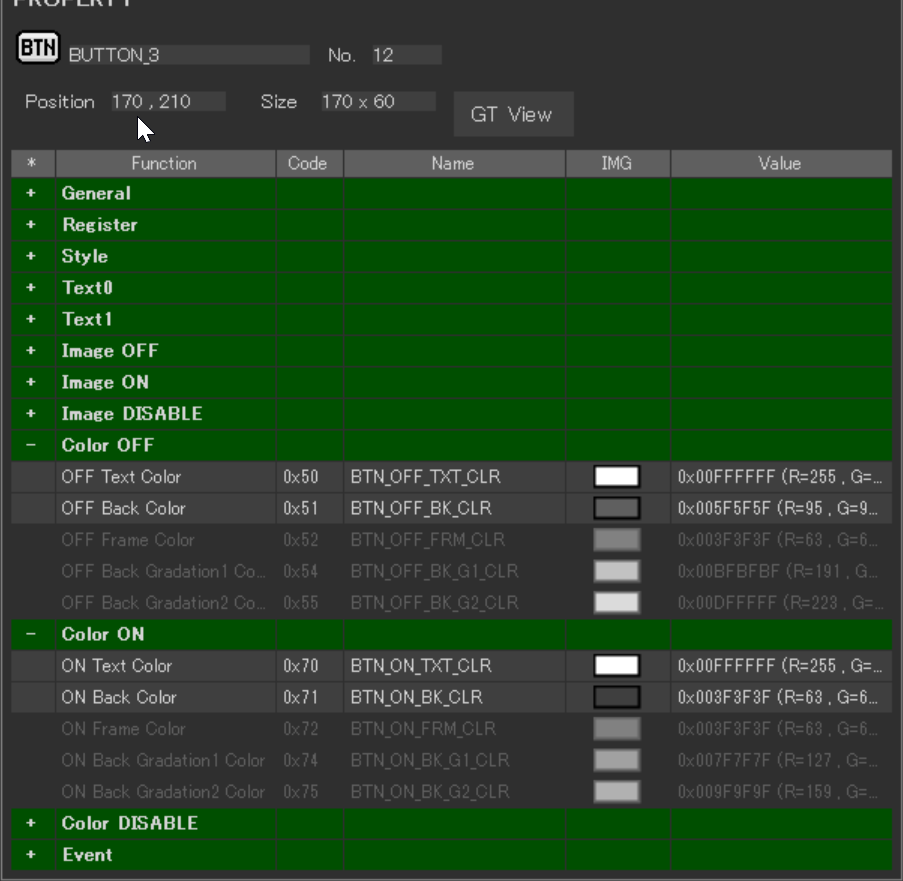
From the BUTTON properties, set the OFF Text Color (when the button is not pressed) to 0x00FFFFFF and the OFF Back Color to 0x005F5F5F. For the Color ON (when the button is pressed), set the ON Text Color to 0x00FFFFFF and the ON Back Color to 0x003F3F3F.
In addition, we will set the font for the button text (Text0) based on the guidelines from the previous article.
Introducing Three New Pages
In this update, we are introducing three distinct pages. The first page is dedicated to slider operations. On this page, we have placed a slider, and objects that display the “minimum angle,” “maximum angle,” and the current angle of the servo motor.
The second page is designed for setting the “minimum angle” and “maximum angle” of the slider. Both the first and second pages include buttons for switching between pages.
The third page features an error message popup for the slider. This popup appears when the “minimum angle” or “maximum angle” settings on the second page fall outside the slider’s designated range (outside 0 degrees to 180 degrees).

Page Switching Events
Buttons for navigating between pages (“BUTTON_0” and “BUTTON_2”) are provided on “PAGE_0” and “PAGE_1”, respectively. During navigation, the Arduino is informed of the current page via “DATA_TX_FIX”, which transmits the name of each page.
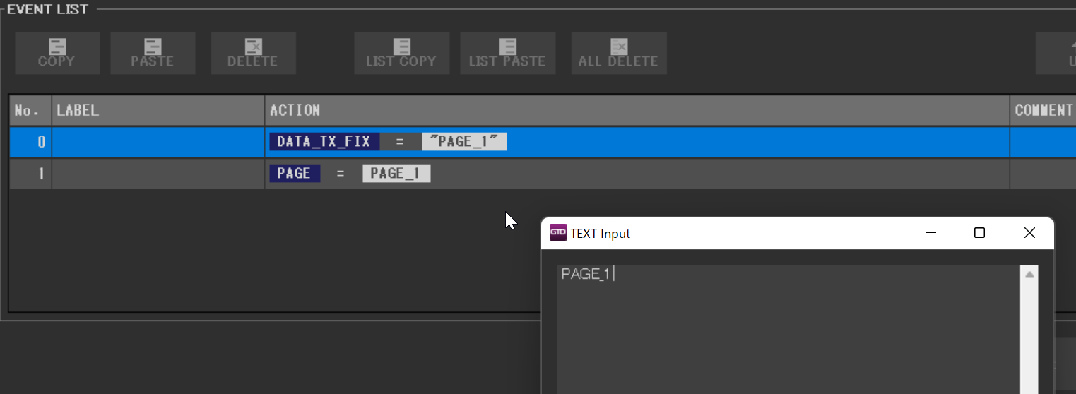
The photo shows the Event Edit window for ‘BUTTON_0’ on PAGE_0. In the DATA_TX_FIX’s VAL field, ‘PAGE_1’ is entered as TEXT for ‘BUTTON_0’. Similarly, ‘PAGE_0’ is set for ‘BUTTON_2’ located on PAGE_1. By incorporating these prefixes, the program is able to adjust its operations accordingly.
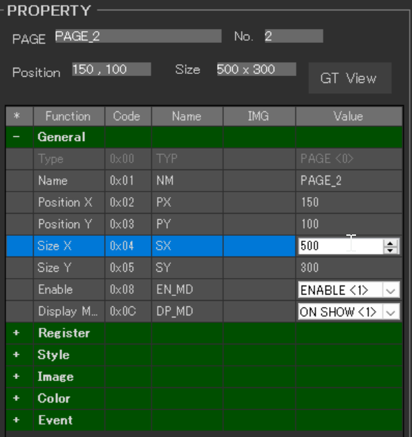
Resizing the Third Page
The third page, which is the error page used as a popup, requires size adjustments.
In the properties of the third page (PAGE_2), change the General > Size X and Size Y values. For this update, set Size X to ‘500’ and Size Y to ‘300’.
Description of Objects on Each Page:
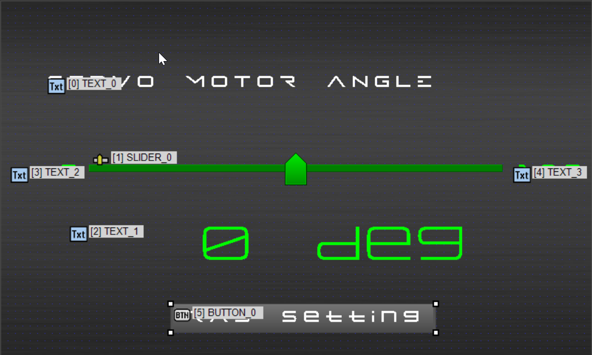
About PAGE_0
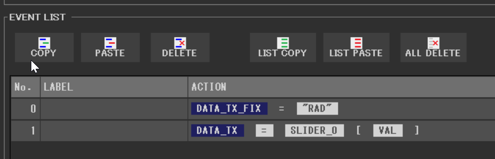
PAGE_0 is the main screen displaying the slider. The difference from the previous project is the addition of text objects “TEXT_2” and “TEXT_3” on either side of the slider, which display the “minimum angle” and “maximum angle”, respectively. Additionally, a button object “BUTTON_0” has been placed at the bottom to switch to the settings page for adjusting angles.
Changes have also been made to the slider object’s event settings; it is now configured to send ‘RAD’ as a prefix via DATA_TX_FIX.
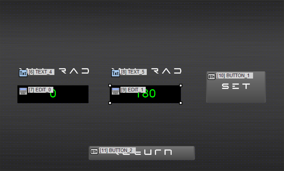
About PAGE_1
This page is designed for setting the “minimum angle” and “maximum angle” of the servo motor.
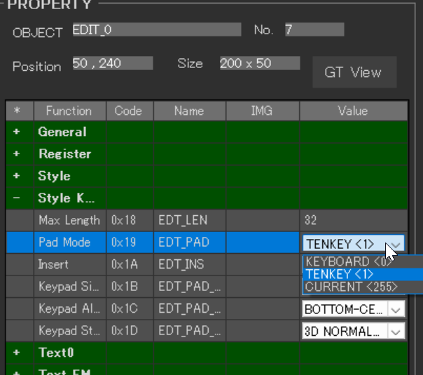
Two edit objects are provided for numeric input. In the properties of these edit objects, set Style Keypad > Pad Mode to “TENKEY”. This allows you to switch from the default alphanumeric keyboard to a numeric-only input pad.
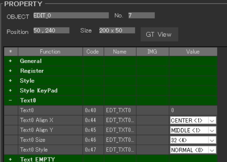
Additionally, as default values for the “minimum angle” and “maximum angle”, set ‘0’ in the Text 0 > Text 0 field of the edit object “EDIT_0”, and ‘180’ in the Text 0 > Text 0 field of the edit object “EDIT_1”.
The design settings for the EDIT objects are set as follows.
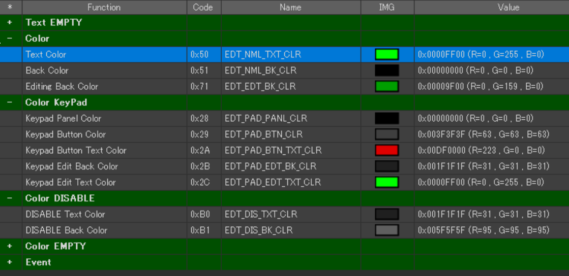
For this iteration, we have chosen a design based on black, as shown in the image. We set various colors under the properties of the EDIT objects: Color, Color KeyPad, and Color DISABLE.
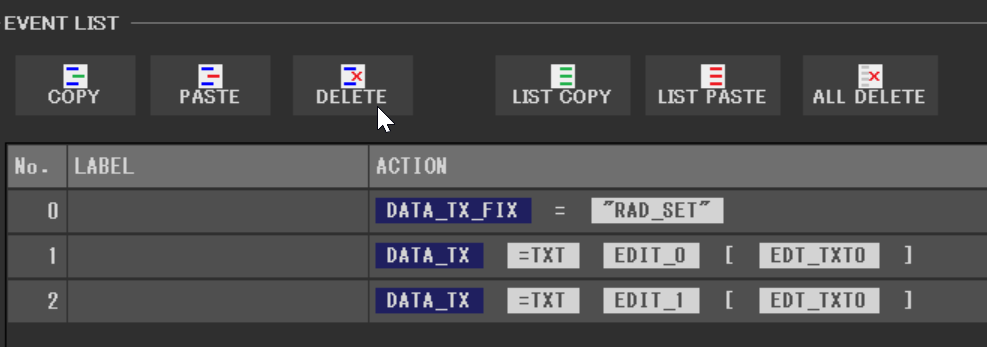
As for the event settings, “BUTTON_1” is configured to use ‘RAD_SET’ as a prefix in DATA_TX_FIX. This setup allows the numerical values entered into the edit objects (stored in Text 0 > Text 0) to be transmitted via DATA_TX.
About PAGE_2
PAGE_2 is a popup page designed to display an error when the angle range does not fall within 0-180 degrees, or when the minimum angle exceeds the maximum angle.
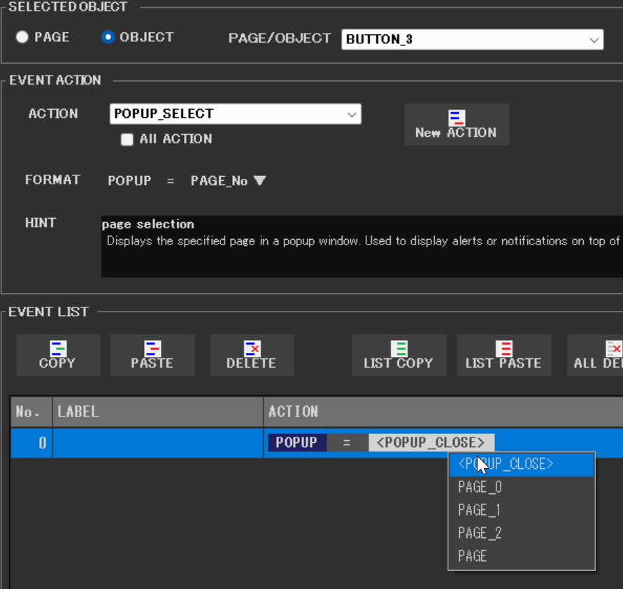
For the button object labeled “Close” (“BUTTON_3”), a POPUP event is assigned. From the Event Edit’s ACTION section, select “POPUP_SELECT”. Once a NEW ACTION is added, choose “<POPUP_CLOSE>”.
Creating a Project for Writing to a Touchscreen
The program prepared for this occasion includes elements that determine the GT-SP’s page, allowing for corresponding processing. On “PAGE_0,” we have precise control over the servo motor’s movements, while “PAGE_1” allows for specialized operations like setting the slider’s range. Additionally, actions are implemented to indicate errors when values outside the slider’s range are set.
Specifically,
Page Management:
- Added a New Variable to Indicate the Current Page
- When a string that begins with “PAGE” is received, it is recognized as a command to change pages, and the variable indicating the current page is updated accordingly.
- When a string that does not start with “PAGE” is received, processes specific to the current page are executed.
Function Addition:
- A function to read strings has been added.
Processing for Each Page:
- The
processPAGE_0function handles operations on “PAGE_0,” primarily relating to the servo motor’s movements. The range for the slider is specified by RAD_min and RAD_max. - The
processPAGE_1function processes operations on “PAGE_1.” Here, when a signal starting with “RAD_SET” is received, the subsequent MIN and MAX values are stored in variables.
Error Checking and Display:
- Checks whether MIN and MAX values are within the appropriate range. If the values are correct, the MIN and MAX values displayed next to the slider bar on PAGE_0 are updated.
- If the values are found to be incorrect, an error dialog popup window is displayed.
Page Control Features:
- A function for page control has been added.
DownloadDownload sample project & program (for GT Design Studio & Arduino)
|
1 2 3 4 5 6 7 8 9 10 11 12 13 14 15 16 17 18 19 20 21 22 23 24 25 26 27 28 29 30 31 32 33 34 35 36 37 38 39 40 41 42 43 44 45 46 47 48 49 50 51 52 53 54 55 56 57 58 59 60 61 62 63 64 65 66 67 68 69 70 71 72 73 74 75 76 77 78 79 80 81 82 83 84 85 86 87 88 89 90 91 92 93 94 95 96 97 98 99 100 101 102 103 104 105 106 107 108 109 110 111 112 113 114 115 116 117 118 119 120 121 122 123 124 125 126 127 128 129 130 131 132 133 134 135 136 137 138 139 140 141 142 143 144 145 146 147 148 149 150 151 152 153 154 155 156 157 158 159 160 161 162 163 164 165 166 167 168 169 170 171 172 173 174 175 176 177 178 179 180 181 182 183 184 185 186 187 188 189 190 191 192 193 194 195 196 197 198 199 200 |
#include <Servo.h> //ピン接続 | Pin assign #define GT_DTR 4 //DTR #define GT_DSR 6 //DSR #define GT_TRDY 7 //TRDY <--未使用 | unused in this sample #define RX_PIN 13 // GT-SPからのシリアルデータを受け取るピン | Pin to receive serial data from GT-S Servo servoMotor; String currentPage; long RAD_min; long RAD_max; void setup() { //ピン初期設定 | Pin setting pinMode(GT_DTR, INPUT); pinMode(GT_DSR, OUTPUT); pinMode(GT_TRDY, INPUT); // Servoモータの初期化 servoMotor.attach(RX_PIN); // シリアル通信の開始 | Start serial communication Serial.begin(38400); //38400bps Baud rate Serial.setTimeout(100); //シリアルタイムアウト | Serial timeout // 開始ページの初期化 | Initialize starting page currentPage = "PAGE_0"; //サーボモーター角度の初期化 | Initialize servo motor angles RAD_min = 0; RAD_max = 180; } void loop() { //GT-SPデータ受信 | Receive one GT-SP response data if ( Serial.available() ) { String receivedData = gtsp_signal_read(); //Serial.println(receivedData); // 受け取ったデータをシリアルモニタに表示 | Display received data on serial monitor if (receivedData.startsWith("PAGE")){ //ページ移動だった場合、現在ページ変数を更新 | Update current page variable if page navigation currentPage = receivedData; }else{ //ページ移動ではない場合、現在のページごとの処理に飛ぶ | Jump to the current page's specific processing if not page navigation if (currentPage == "PAGE_0") { processPAGE_0(receivedData); }else if (currentPage == "PAGE_1") { processPAGE_1(receivedData); } } } } //////////////////////////////////////////////////// //PAGE_0の処理 | Process - PAGE_0 //////////////////////////////////////////////////// void processPAGE_0(String data){ //スライダー操作処理 | Slider operation processing if (data.startsWith("RAD")){ //スライダーの値を取得 | Get slider value unsigned long gtspValue = gtsp_signal_read_numeric(); //Serial.println(gtspValue); // 受け取ったデータをシリアルモニタに表示 | Display received data on serial monitor // スライダーの値をRAD_min〜RAD_maxの範囲にマッピング | Mapping slider values to the range of RAD_min to RAD_max int servoAngle = map(gtspValue, 0, 1023, RAD_min, RAD_max); // サーボモータを指定した角度に動かす | Move servo motor to the specified angle servoMotor.write(servoAngle); // GT-SPにサーボモータの角度を表示 | Display servo motor angle on GT-SP gtsp_ObjPrpSet_string(2, 0x40, String(servoAngle)+ " deg"); } } //////////////////////////////////////////////////// //PAGE_1の処理 | Process - PAGE_1 //////////////////////////////////////////////////// void processPAGE_1(String data){ //設定値の取得 | Retrieval of settings if (data.startsWith("RAD_SET")){ RAD_min = gtsp_signal_read().toInt(); //最小値の取得 | Retrieve minimum value RAD_max = gtsp_signal_read().toInt(); //最大値の取得 | Retrieve maximum value } //設定値のエラーチェックと更新 | Check and update settings for errors if (RAD_min >= 0 && RAD_max <=180 && RAD_min < RAD_max ){ // PAGTE_0 スライダー横のMIN MAX数値を更新 | Update MIN MAX numbers next to the slider on PAGE_0 gtsp_ObjPrpSet_string(3, 0x40, String(RAD_min)); gtsp_ObjPrpSet_string(4, 0x40, String(RAD_max)); }else{ //値の設定値が正しくないときは、エラーダイアログをPOPUPで表示 | Display error dialog if the settings values are incorrect gtsp_ObjPrpSet_string(13, 0x40, "RAD Value Error"); //エラーメッセージの変更 | Change error message gtsp_PgControl(0x20, 2); //エラーダイアログPOPUP表示 | Display error dialog POPUP } } /********************** 関数 | Function **********************/ //////////////////////////////////////////////////// // データ受信(文字列用) | Receive data from GT-SP (for String) //////////////////////////////////////////////////// String gtsp_signal_read(){ byte res_dl[4] = ""; unsigned long dl; char res_data_char[255]=""; if (Serial.find("RESb", 4)){ Serial.readBytes(res_dl, 4); //データ長抽出 | Read data length dl = (unsigned long)(res_dl[0] + (res_dl[1]<<8) + (res_dl[2]<<16) + (res_dl[3]<<24)); //データ長変換 | Data length Serial.readBytes(res_data_char, dl); //データ抽出 | Read data return String(res_data_char); //String型変換、リターン | Return as String } } //////////////////////////////////////////////////// // データ受信(数値用) | Receive data from GT-SP (for Numeric) //////////////////////////////////////////////////// unsigned long gtsp_signal_read_numeric() { byte res_dl[4] = ""; unsigned long dl; if (Serial.find("RESb", 4)) { Serial.readBytes(res_dl, 4); //データ長抽出 | Read data length dl = (unsigned long)(res_dl[0] + (res_dl[1] << 8) + (res_dl[2] << 16) + (res_dl[3] << 24)); //データ長変換 | Data length // 数値を受信するためのバッファ byte res_data_buffer[4]; // データを読み取り Serial.readBytes(res_data_buffer, dl); // 数値に変換してリターン return (unsigned long)(res_data_buffer[0] + (res_data_buffer[1] << 8) + (res_data_buffer[2] << 16) + (res_data_buffer[3] << 24)); } // エラー時は0を返す(適切なエラー処理が必要な場合は修正が必要) return 0; } //////////////////////////////////////////////////// // オブジェクト制御コマンド - プロパティ設定 (文字列用) | Object Control Command -Property Setting (for String) //////////////////////////////////////////////////// void gtsp_ObjPrpSet_string(int obj, int prp, String val ) { gt_print("CMD"); //コマンドヘッダ | Command header gt_put(0xd3); //オブジェクト-プロパティ設定コマンド | Object-Property Setting gt_put(obj >> 0); //オブジェクトNo. 下位バイト | Object No. Lower byte gt_put(obj >> 8); //オブジェクトNo. 上位バイト| Object No. Upper byte gt_put(prp >> 0); //プロパティNo. 下位バイト | Property No. Lower byte gt_put(prp >> 8); //プロパティNo. 上位バイト| Property No. Upper byte gt_put(val.length() >> 0); //データ長 最下位バイト | Data length Least significant byte gt_put(val.length() >> 8); //データ長 下位バイト | Data length second byte gt_put(val.length() >> 16); //データ長 上位バイト | Data length third byte gt_put(val.length() >> 24); //データ長 最上位バイト| Data length Most significant byte gt_print(val); //文字列送信 // Send string } //////////////////////////////////////////////////// // GUIページ制御/POPUP制御 | GUI PAGE/POPUP Control Command //////////////////////////////////////////////////// void gtsp_PgControl(int typ, int pg) { gt_print("CMD"); //コマンドヘッダ | Command header gt_put(0xfb); //UIページ制御/POPUP制御設定コマンド | Object-Property Setting gt_put(typ); //制御タイプ | Type (10h:PAGE Select, 20h:POPUP Open, 21h, POPUP Close) gt_put(pg >> 0); //PAGE No. 下位バイト | Page No. Lower byte gt_put(pg >> 8); //PAGE No. 上位バイト| Page No. Upper byte } //////////////////////////////////////////////////// // 1byte送信 | Send byte to GT-SP //////////////////////////////////////////////////// void gt_put(unsigned char onebyte) { while ( digitalRead(GT_DTR) == HIGH ) {} //busycheck Serial.write(onebyte); } //////////////////////////////////////////////////// // 文字列送信 | Send String to GT-SP //////////////////////////////////////////////////// void gt_print(String val) { int val_i; //文字列を1文字ずつ送信 | Send string per one byte for (val_i = 0; val_i < val.length(); val_i++) { while ( digitalRead(GT_DTR) == HIGH ) {} //busycheck Serial.print(val.substring(val_i, val_i+1)); } } |
Decoding the Program
In the main loop, data starting with “PAGE” is recognized as a page transition, and other data triggers processes specific to the current page.
In processPAGE_0, the servo motor’s angle is adjusted. Specifically, data beginning with “RAD” is received, and its value is mapped to the servo motor’s operational range to change the angle. In processPAGE_1, the operational range of the servo motor (minimum and maximum angles) is set. Data beginning with “RAD_SET” is used to read the minimum and maximum values, which are then checked to ensure they are within the range before updating the variables.
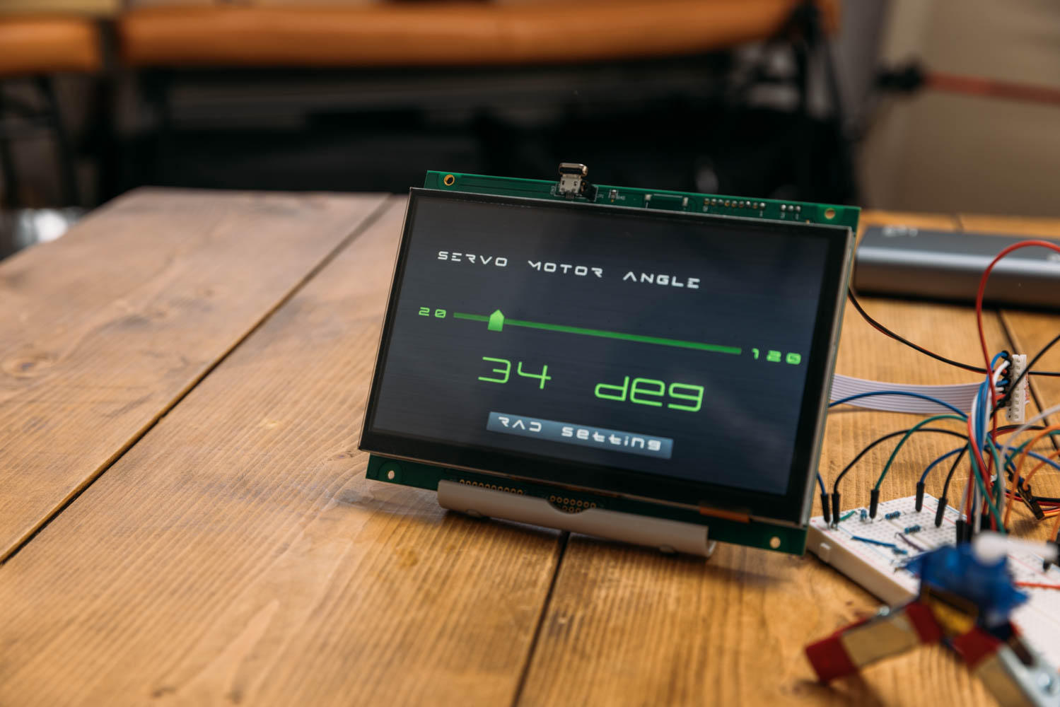
Execution Results
This project is an enhancement of the previous project, now utilizing the GT-SP display to allow users to directly adjust the operational range of the servo motor. This improvement enables users to easily set the necessary operational ranges for specific applications, which holds significant importance. The flexible range setting feature is applicable to a variety of applications, opening up new possibilities for projects using Arduino and GT-SP.
Moreover, the use of prefixes to differentiate operations suggests promising potential for future program development.
In our next session, we will tackle a project to control the lighting status of LEDs from the display.