
Series: Using the GT-SP Touch Panel TFT Display with Arduino
UI Control of GT-SP Display Using an Infrared Receiver Module
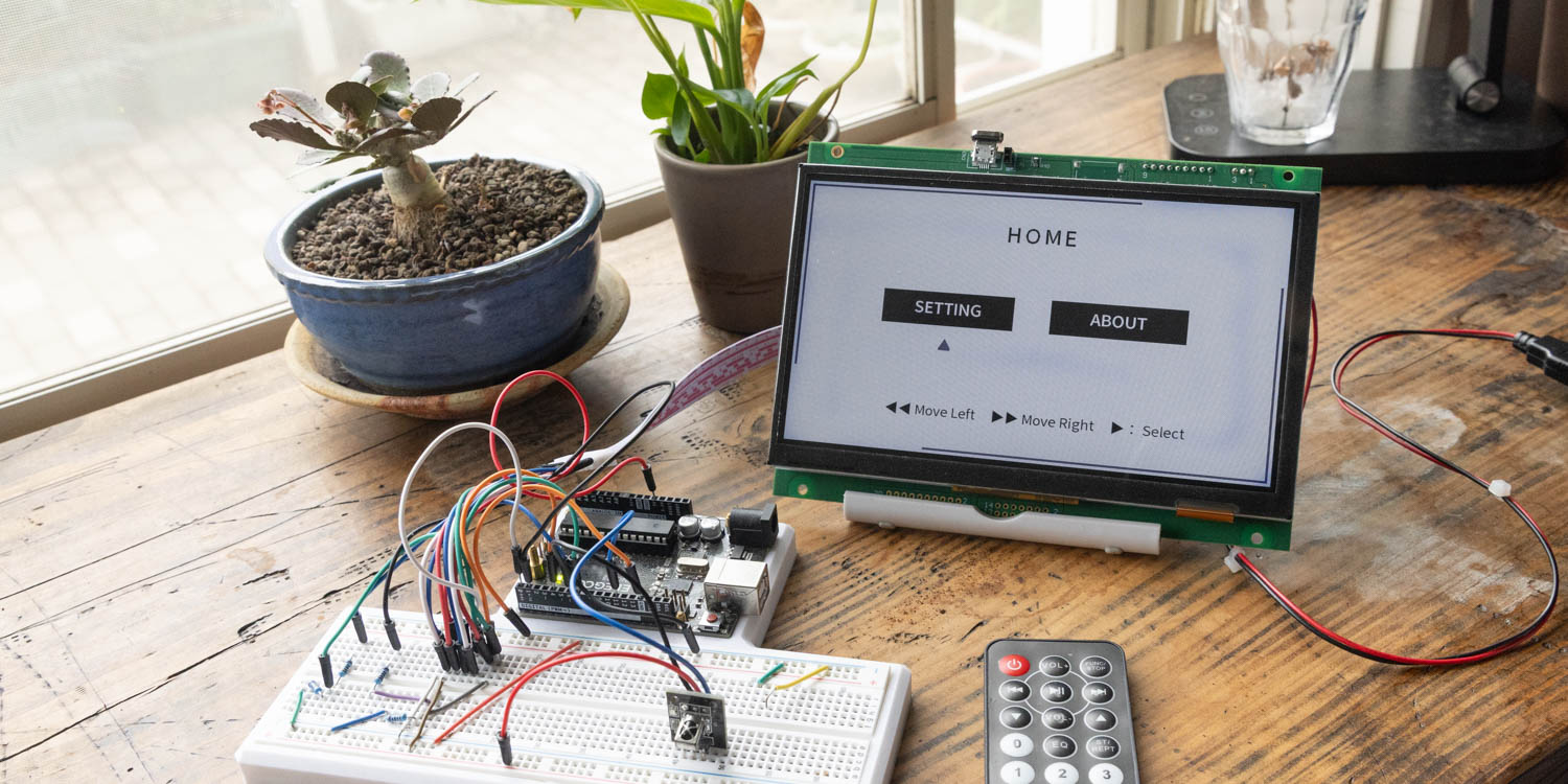
Table of Contents
DownloadDownload sample project & program (for GT Design Studio & Arduino)
Hello everyone, I’m @kissaten, a beginner in electronics. In this series, I’m explaining the process of connecting a 7-inch touch display (GT-SP series “GTWV070S3A00P”) to an Arduino and working on various projects.
In this article, we will explain the process of creating an application that controls screen transitions and the backlight brightness of the GT-SP display from a remote control using an infrared receiver module. We will also touch on troubleshooting communication conflicts when handling both infrared signal reception and display control on a single microcontroller, as well as synchronizing states with touch panel operations.
Hardware Connection and Library Preparation
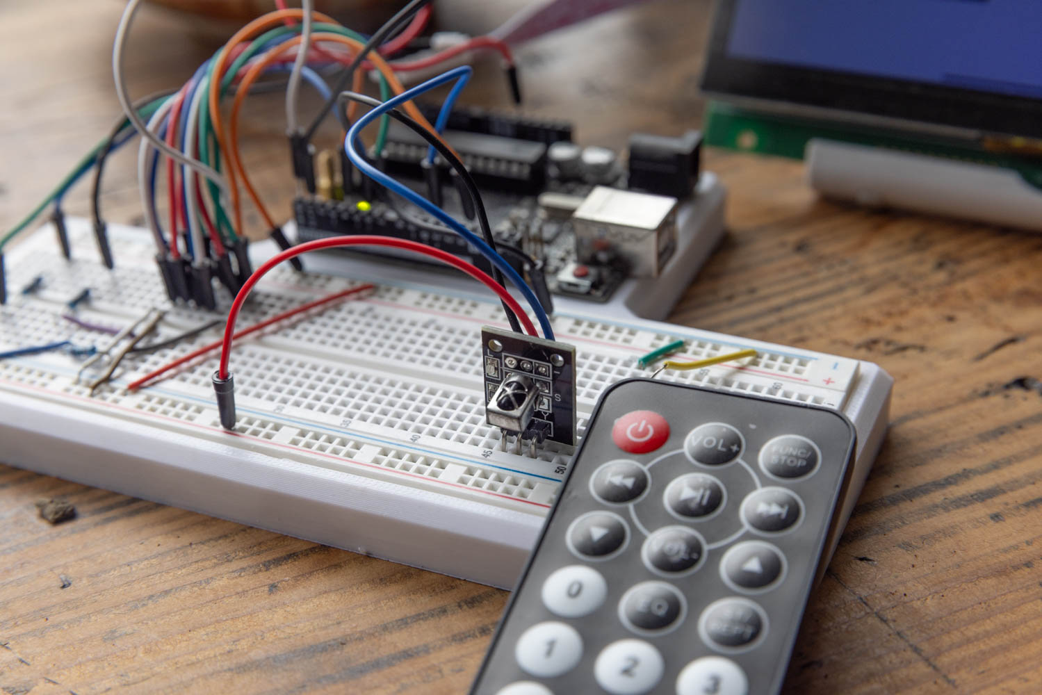
In this project, we will add a commercially available infrared receiver module and an infrared remote control to the Arduino and GT-SP display environment we have built in previous articles.
Hardware Pin Connection
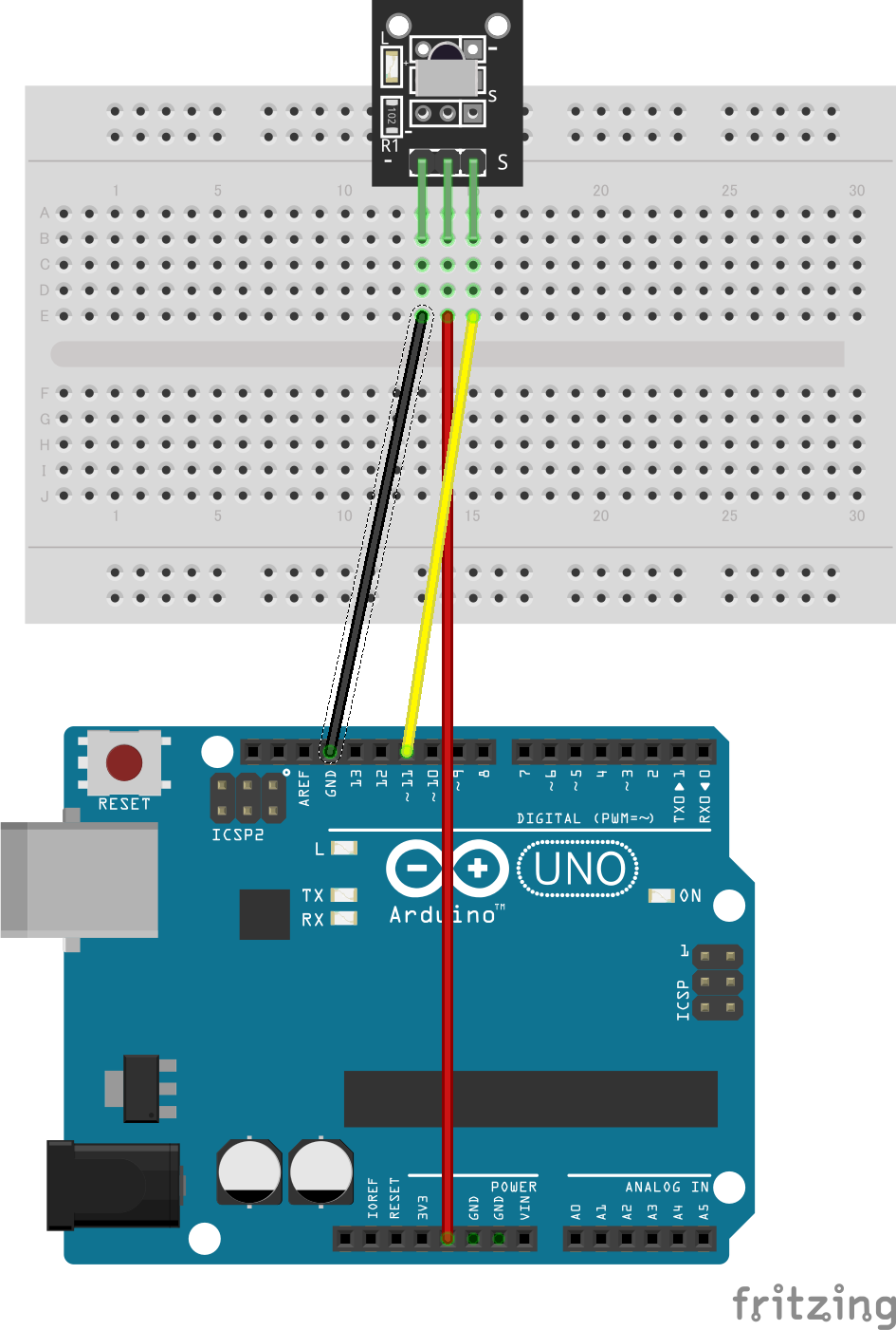
This assumes the Arduino and GT-SP display are already connected via serial communication and control pins. We will connect the infrared module as an addition as follows.
[Arduino Side] [Infrared Module Side]
- 5V ⇔ VCC
- GND ⇔ GND
- Pin 11 Data ⇔ Output
Picture by [FritzingCC BY-SA)]
「KY-022 Infrared Receiver Module Fritzing Part」by [arduinomodules.infoLicense (CC BY-SA 4.0)]
Installing the Library
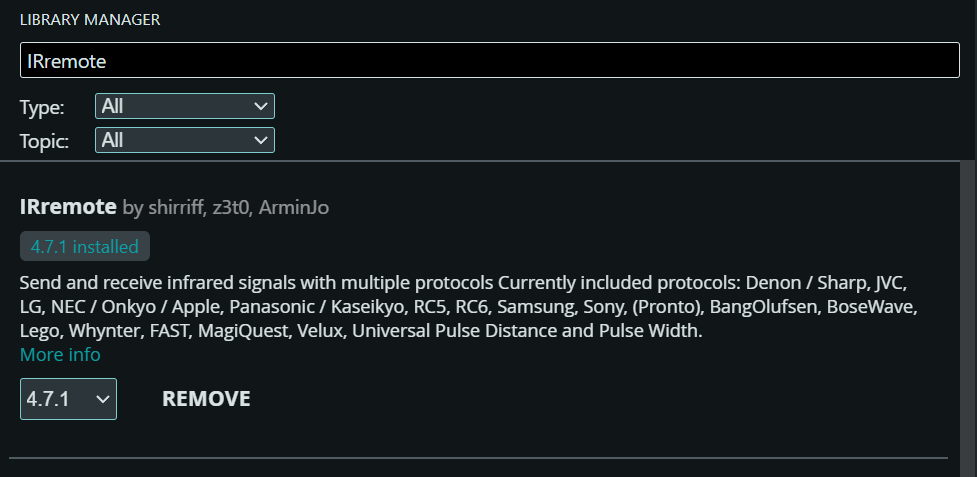
We will use an external library to analyze the infrared signals. From the Arduino IDE menu, open “Sketch” > “Include Library” > “Manage Libraries…”, and type “IRremote” in the search box. Find the “IRremote” library in the search results and install it.
Measurement and Confirmation of Infrared Codes
The signals transmitted when a remote control button is pressed vary depending on the remote control model. Therefore, you first need to identify the hexadecimal codes assigned to each button on the remote you are using.
Write the following infrared analysis sketch to the Arduino and open the Serial Monitor (38400bps).
|
1 2 3 4 5 6 7 8 9 10 11 12 13 14 15 16 17 18 19 20 21 22 23 24 25 26 |
#include #include // 赤外線ライブラリ | IRremote library // ピン接続 | Pin assign #define IR_RECEIVE_PIN 11 // 赤外線受信ピン | IR Receiver Pin void setup() { // シリアル通信の開始 | Start serial communication Serial.begin(38400); // 38400bps Baud rate // 赤外線受信の開始 | Start the receiver IrReceiver.begin(IR_RECEIVE_PIN, ENABLE_LED_FEEDBACK); } void loop() { // 赤外線信号を受信したか判定 | Check if IR signal is received if (IrReceiver.decode()) { // 受信したコマンドを16進数で表示 | Print received command in HEX Serial.print("Command: 0x"); Serial.println(IrReceiver.decodedIRData.command, HEX); // 次の信号を受信する準備 | Receive the next value IrReceiver.resume(); } } |
When you press a button on the remote while pointing it at the receiver in this state, the code will be displayed in the Serial Monitor in a format like “Command: 0x45”.
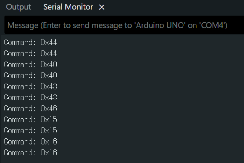
In this sample, we will build the system by assigning the following codes to each operation based on the measurement results.
POWER Button: 0x45 Rewind (Move Left) Button: 0x44 Fast Forward (Move Right) Button: 0x43 Play (Select) Button: 0x40 VOL+ Button: 0x46 VOL- Button: 0x15 0 Button: 0x16
Application UI Design
Using GT Design Studio, we will create three screens with different purposes and assign remote control operations to each.
Page 0: HOME
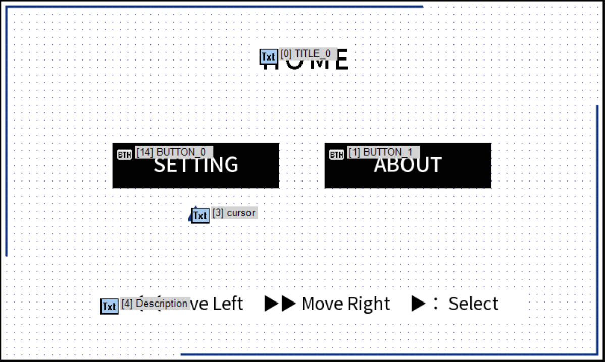
A selection screen with a side-by-side menu and a cursor. Use the left and right buttons on the remote to move the cursor, and the select button to transition to the corresponding page.
Page 1: SETTING
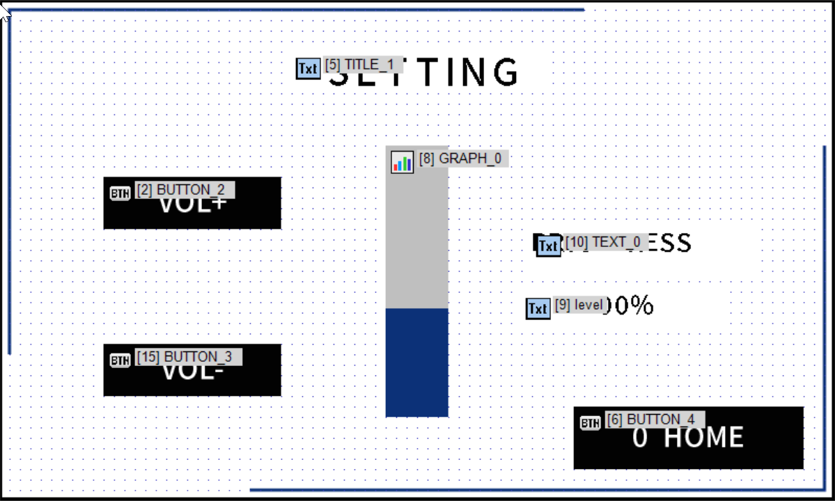
A display brightness adjustment screen using a separate bar graph (Property ID: 0x40). The brightness can be adjusted in approximately 20% increments using the VOL+ and VOL- buttons.
Page 2: ABOUT
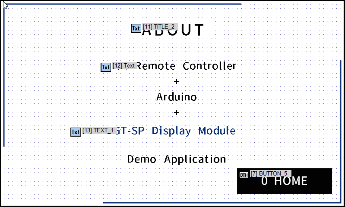
An explanation screen showing the system configuration, etc.
As a common operation across all screens, pressing the 0 button returns to the HOME screen, and the POWER button toggles the display on and off.
Bidirectional Synchronization with the Touch Panel
If page transitions or brightness adjustments are made via touch panel operations rather than the remote control, inconsistencies easily occur between the state variables held by the Arduino and the actual screen state.
To solve this, we set a single-character serial transmission in the touch action properties for each button in GT Design Studio as follows.
- When HOME button is pressed: h
- When SETTING button is pressed: s
- When ABOUT button is pressed: a
- When VOL+ button is pressed: u
- When VOL- button is pressed: d
By having the Arduino receive these characters and update its internal variables, we achieve state synchronization between the remote control and the touch panel at a practically problem-free level, even if it is not a completely simultaneous operation.
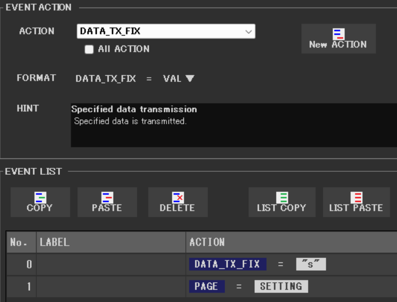
The image above is an example of the event when the SETTING button is pressed. It sets an event that uses DATA_TX_FIX to send “s” to the Arduino and an event to jump to the SETTING page.
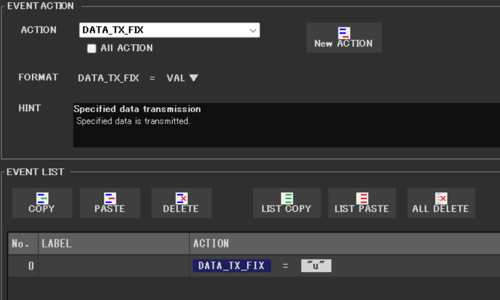
The image above is an example of the event when the VOL+ button is pressed. It is an event that sends “u” to the Arduino using DATA_TX_FIX. The program receives this and increases the screen brightness.
Arduino Program
This is the source code for Arduino that implements the specifications and countermeasures mentioned above. The dedicated functions for GT-SP are placed according to the specifications, and the infrared reception processing and serial reception processing are branched within the main loop.
DownloadDownload sample project & program (for GT Design Studio & Arduino)
|
1 2 3 4 5 6 7 8 9 10 11 12 13 14 15 16 17 18 19 20 21 22 23 24 25 26 27 28 29 30 31 32 33 34 35 36 37 38 39 40 41 42 43 44 45 46 47 48 49 50 51 52 53 54 55 56 57 58 59 60 61 62 63 64 65 66 67 68 69 70 71 72 73 74 75 76 77 78 79 80 81 82 83 84 85 86 87 88 89 90 91 92 93 94 95 96 97 98 99 100 101 102 103 104 105 106 107 108 109 110 111 112 113 114 115 116 117 118 119 120 121 122 123 124 125 126 127 128 129 130 131 132 133 134 135 136 137 138 139 140 141 142 143 144 145 146 147 148 149 150 151 152 153 154 155 156 157 158 159 160 161 162 163 164 165 166 167 168 169 170 171 172 173 174 175 176 177 178 179 180 181 182 183 184 185 186 187 188 189 190 191 192 193 194 195 196 197 198 199 200 201 202 203 204 205 206 207 208 209 210 211 212 213 214 215 216 217 218 219 220 221 222 223 224 225 226 227 228 229 230 231 232 233 234 235 236 237 238 239 240 241 242 243 244 245 |
#include <Arduino.h> #include <IRremote.hpp> // 赤外線ライブラリ | IRremote library #include <string.h> // ピン接続 | Pin assign #define GT_DTR 4 // DTRピン | DTR pin #define GT_DSR 6 // DSRピン | DSR pin #define IR_RECEIVE_PIN 11 // 赤外線受信ピン | IR Receiver Pin // 変数設定 | Variable setting int current_brightness = 255; // 明るさ現在値(0-255) | Current brightness const int brightness_step = 51; // 変更ステップ(約20%) | Brightness step const int min_brightness = 0; // 最小明るさ | Minimum brightness bool is_display_on = true; // 画面表示状態 | Display power state // 状態管理変数 | State management variables int current_page = 0; // 現在のページ(0:HOME, 1:SETTING, 2:ABOUT) | Current page int cursor_pos = 0; // カーソル位置(0:左/SETTING, 1:右/ABOUT) | Cursor position // 連続入力防止用の変数 | Variables for preventing continuous input unsigned long last_ir_time = 0; // 前回赤外線を処理した時間 | Last IR processed time const unsigned long IR_COOL_TIME = 200; // クールタイム(ミリ秒) | Cool time (milliseconds) // GT Design Studioで設定したプロパティID | Property IDs set in GT Design Studio const int PROP_CURSOR_X = 0x02; // カーソル(No3)のPosition X プロパティID | Position X Property ID of Cursor (No3) const int PROP_GRAPH_VAL = 0x40; // グラフ(No8)のValue プロパティID | Value Property ID of Graph (No8) const int PROP_TEXT_STR = 0x40; // テキスト(No9)のText プロパティID | Text Property ID of Text (No9) void setup() { pinMode(GT_DTR, INPUT); pinMode(GT_DSR, OUTPUT); digitalWrite(GT_DSR, LOW); Serial.begin(38400); Serial.setTimeout(100); IrReceiver.begin(IR_RECEIVE_PIN, ENABLE_LED_FEEDBACK); delay(1000); // 起動時の初期輝度を設定 | Set initial brightness set_gtsp_brightness(current_brightness); // 初期画面をHOME(ページ0)に設定 | Set initial page to HOME gtsp_PgControl(0x10, 0); // 起動時に現在の明るさをグラフとテキストに同期させておく | Sync current brightness to UI update_brightness(0); } void loop() { // 1. 赤外線リモコンからの操作処理 | 1. IR Remote operation processing if (IrReceiver.decode()) { unsigned long current_time = millis(); // 現在の時間を取得 | Get current time // クールタイムが経過しているかチェック | Check if cool time has passed if (current_time - last_ir_time > IR_COOL_TIME) { unsigned long ir_code = IrReceiver.decodedIRData.command; // 全画面共通:POWERボタン(0x45) | Common: POWER button if (ir_code == 0x45) { is_display_on = !is_display_on; if (is_display_on) { set_gtsp_brightness(current_brightness); // 復帰 | Resume } else { set_gtsp_brightness(0); // 仮の消灯処理 | Temporary turn off } } // HOME画面(Page 0)の時の操作 | Operation on HOME screen else if (current_page == 0) { if (ir_code == 0x44) { // ◀◀ 左移動 | Move Left cursor_pos = 0; gtsp_ObjPrpSet_val(3, PROP_CURSOR_X, 4, 250); gtsp_PgControl(0x10, 0); // ページ0をリロードして反映させる | Reload page 0 to reflect } else if (ir_code == 0x43) { // ▶▶ 右移動 | Move Right cursor_pos = 1; gtsp_ObjPrpSet_val(3, PROP_CURSOR_X, 4, 530); gtsp_PgControl(0x10, 0); // ページ0をリロードして反映させる | Reload page 0 to reflect } else if (ir_code == 0x40) { // ▶ 決定 | Enter if (cursor_pos == 0) { current_page = 1; gtsp_PgControl(0x10, 1); // SETTING(ページ1)へ | Go to SETTING (Page 1) update_brightness(0); // 画面遷移時にグラフとテキストを同期 | Sync graph and text on page transition } else { current_page = 2; gtsp_PgControl(0x10, 2); // ABOUT(ページ2)へ | Go to ABOUT (Page 2) } } } // SETTING画面(Page 1)の時の操作 | Operation on SETTING screen else if (current_page == 1) { if (ir_code == 0x46) { // VOL+ | VOL+ update_brightness(brightness_step); } else if (ir_code == 0x15) { // VOL- | VOL- update_brightness(-brightness_step); } else if (ir_code == 0x16) { // 0ボタン | 0 button current_page = 0; gtsp_PgControl(0x10, 0); // HOMEへ戻る | Return to HOME } } // ABOUT画面(Page 2)の時の操作 | Operation on ABOUT screen else if (current_page == 2) { if (ir_code == 0x16) { // 0ボタン | 0 button current_page = 0; gtsp_PgControl(0x10, 0); // HOMEへ戻る | Return to HOME } } // 最後に処理した時間を更新 | Update last processed time last_ir_time = current_time; } // クールタイム中であっても、受信バッファは常に空にして次の信号に備える | Always clear the receive buffer for the next signal even during cool time IrReceiver.resume(); } // 2. 画面のタッチ操作(シリアル受信)処理 | 2. Touch operation (Serial receive) processing if (Serial.available() > 0) { char touch_cmd = Serial.read(); // ページ遷移の報告を受け取って状態を同期する | Receive page transition report and sync state if (touch_cmd == 'h') { current_page = 0; } else if (touch_cmd == 's') { current_page = 1; update_brightness(0); // SETTING画面に来たので明るさUIも同期 | Sync brightness UI as it moved to SETTING screen } else if (touch_cmd == 'a') { current_page = 2; } // SETTING画面(Page 1)の時だけタッチ操作を受け付ける | Accept touch operation only on the SETTING screen (Page 1) if (current_page == 1) { if (touch_cmd == 'u') { update_brightness(brightness_step); // 明るさアップ | Brightness up } else if (touch_cmd == 'd') { update_brightness(-brightness_step); // 明るさダウン | Brightness down } } } } /********************** カスタム関数 | Custom Functions **********************/ void update_brightness(int change_val) { current_brightness = current_brightness + change_val; if (current_brightness > 255) current_brightness = 255; if (current_brightness < min_brightness) current_brightness = min_brightness; set_gtsp_brightness(current_brightness); int percent = (current_brightness * 100) / 255; // グラフとテキストへ送信 | Send to graph and text gtsp_ObjPrpSet_val(8, PROP_GRAPH_VAL, 4, percent); gtsp_ObjPrpSet_string(9, PROP_TEXT_STR, String(percent)); } void set_gtsp_brightness(int val) { gt_print("CMD"); gt_put(0x58); gt_put(val); } /********************** GT-SP関数 | Function for GT-SP **********************/ //////////////////////////////////////////////////// // オブジェクト制御コマンド - プロパティ設定 (数値用) | Object Control Command - Property Setting (for Value) //////////////////////////////////////////////////// void gtsp_ObjPrpSet_val(int obj, int prp, int ln, unsigned long val) { gt_print("CMD"); // コマンドヘッダ | Command header gt_put(0xd3); // オブジェクト-プロパティ設定コマンド | Object-Property Setting gt_put(obj >> 0); // オブジェクトNo. 下位バイト | Object No. Lower byte gt_put(obj >> 8); // オブジェクトNo. 上位バイト | Object No. Upper byte gt_put(prp >> 0); // プロパティNo. 下位バイト | Property No. Lower byte gt_put(prp >> 8); // プロパティNo. 上位バイト | Property No. Upper byte gt_put(ln >> 0); // データ長 最下位バイト | Data length Least significant byte gt_put(ln >> 8); // データ長 下位バイト | Data length second byte gt_put(ln >> 16); // データ長 上位バイト | Data length third byte gt_put(ln >> 24); // データ長 最上位バイト | Data length Most significant byte if (ln >= 1) gt_put(val >> 0); if (ln >= 2) gt_put(val >> 8); if (ln >= 3) gt_put(val >> 16); if (ln >= 4) gt_put(val >> 24); } //////////////////////////////////////////////////// // オブジェクト制御コマンド - プロパティ設定 (文字列用) | Object Control Command - Property Setting (for String) //////////////////////////////////////////////////// void gtsp_ObjPrpSet_string(int obj, int prp, String val ) { gt_print("CMD"); // コマンドヘッダ | Command header gt_put(0xd3); // オブジェクト-プロパティ設定コマンド | Object-Property Setting gt_put(obj >> 0); // オブジェクトNo. 下位バイト | Object No. Lower byte gt_put(obj >> 8); // オブジェクトNo. 上位バイト | Object No. Upper byte gt_put(prp >> 0); // プロパティNo. 下位バイト | Property No. Lower byte gt_put(prp >> 8); // プロパティNo. 上位バイト | Property No. Upper byte gt_put(val.length() >> 0); // データ長 最下位バイト | Data length Least significant byte gt_put(val.length() >> 8); // データ長 下位バイト | Data length second byte gt_put(val.length() >> 16); // データ長 上位バイト | Data length third byte gt_put(val.length() >> 24); // データ長 最上位バイト | Data length Most significant byte gt_print(val); // 文字列送信 | Send string } //////////////////////////////////////////////////// // GUIページ制御/POPUP制御 | GUI PAGE/POPUP Control Command //////////////////////////////////////////////////// void gtsp_PgControl(int typ, int pg) { gt_print("CMD"); // コマンドヘッダ | Command header gt_put(0xfb); // UIページ制御/POPUP制御設定コマンド | Object-Property Setting gt_put(typ); // 制御タイプ | Type (10h:PAGE Select, 20h:POPUP Open, 21h, POPUP Close) gt_put(pg >> 0); // PAGE No. 下位バイト | Page No. Lower byte gt_put(pg >> 8); // PAGE No. 上位バイト | Page No. Upper byte } //////////////////////////////////////////////////// // 文字列送信 | Send string to GT-SP //////////////////////////////////////////////////// void gt_print(String val) { int val_i; // 文字列を1文字ずつ送信 | Send string per one byte for (val_i = 0; val_i < val.length(); val_i++) { while (digitalRead(GT_DTR) == HIGH) {} // 処理待ち確認 | busycheck Serial.print(val.substring(val_i, val_i + 1)); } } //////////////////////////////////////////////////// // 1byte送信 | Send byte to GT-SP //////////////////////////////////////////////////// void gt_put(unsigned char onebyte) { while (digitalRead(GT_DTR) == HIGH) {} // 処理待ち確認 | busycheck Serial.write(onebyte); } |
Mechanism of Cursor Movement
Let’s explain the operation when the left or right buttons on the remote control are pressed on the HOME screen.
Here, we use the “gtsp_ObjPrpSet_val” function to directly overwrite the X coordinate of the cursor on the screen (Object No. 3 in this case) from the Arduino.
If the left button is pressed, the X coordinate is set to 250, and if the right button is pressed, the value is set to 530. After overwriting the values, the “gtsp_PgControl” function is used to reload the page and update the screen display.
Synchronization of Display Brightness and Graph
Let’s explain the operation when the VOL+ and VOL- buttons are pressed on the SETTING screen.
Here, the “update_brightness” function is used to perform addition or subtraction on the current brightness in increments of about 20%.
The calculated brightness value (0-255) is passed to the “set_gtsp_brightness” function, and from there it reaches the display unit as the “0x58” backlight control command to change the actual brightness.
Simultaneously, the program recalculates the “What is the current brightness %?” for UI display, sends it to the graph (Object No. 8) with the “gtsp_ObjPrpSet_val” function, and rewrites the text (Object No. 9) display using the “gtsp_ObjPrpSet_string” function.
Summary
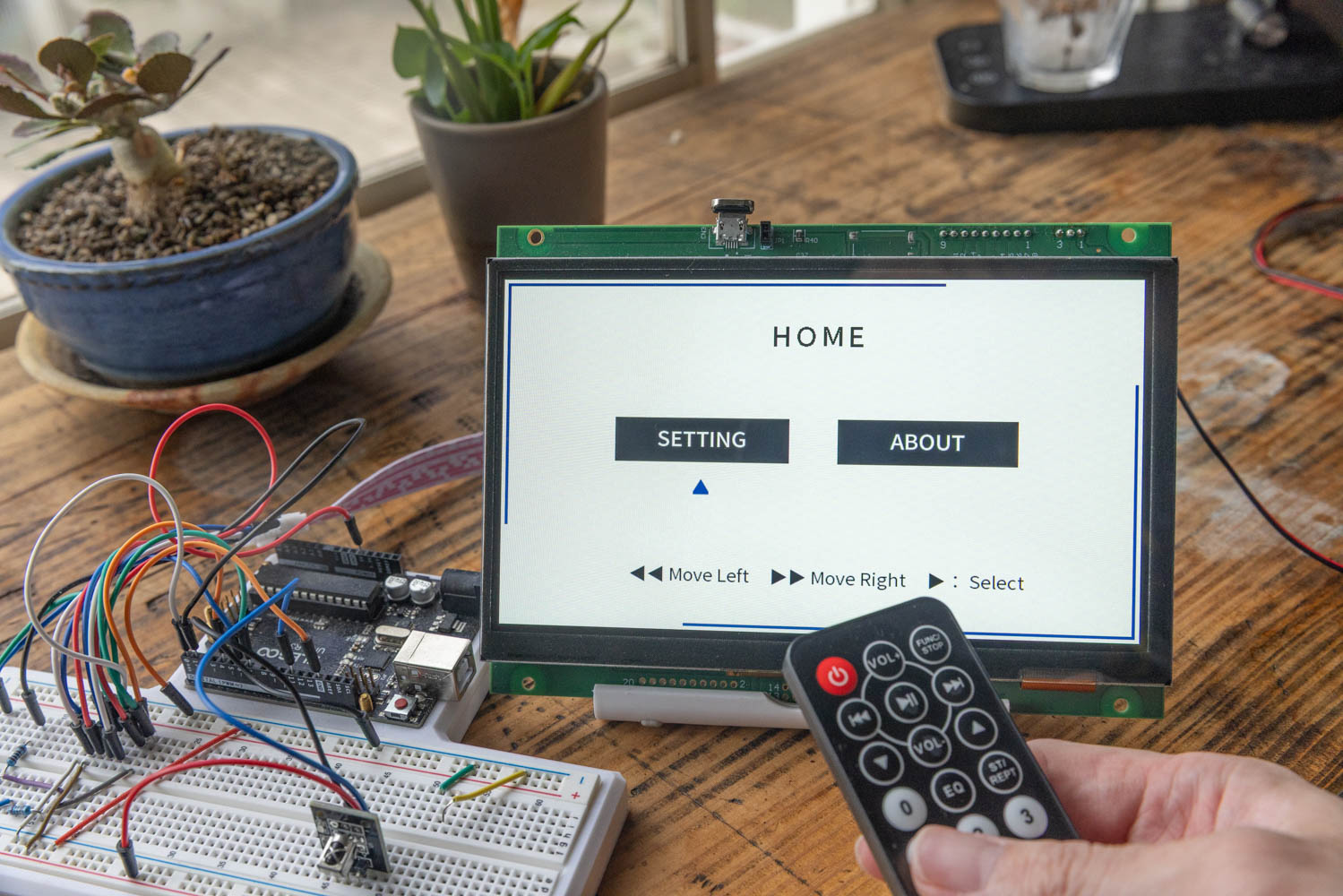
In this article, we explained the method of controlling the UI of the GT-SP display from a remote control using an Arduino and an infrared receiver module.
Communication conflict issues, which are often overlooked when linking different devices, can be avoided by reviewing the processing order on the microcontroller side. Furthermore, in systems with multiple input methods like a touch panel and a physical remote control, a design that properly centralizes state variables on the microcontroller side and synchronizes them with the display side is the key to stable operation.
If you apply this mechanism, the applications of the display will expand even further, not only for remote screen operation but also for automatic control linked with various sensors. Please try incorporating it into your actual projects.