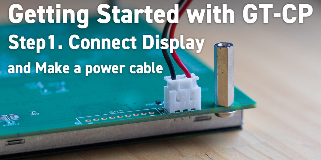
Interested?

* Indicates a required field

- from

GTOMP (BETA) This software is in BETA. We provide this software as a touch sensitivity monitor and touch package data download tool. temp-icon-image-for-gtomp-ver-0977

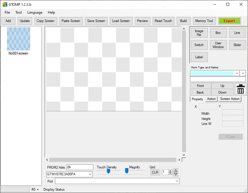
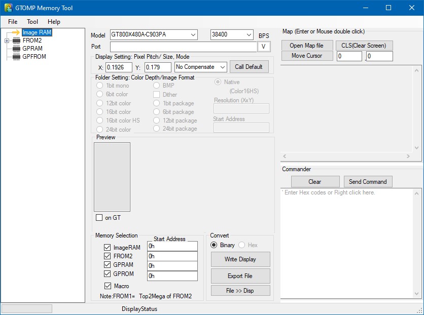
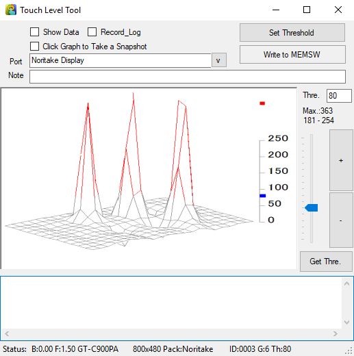
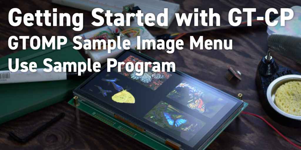
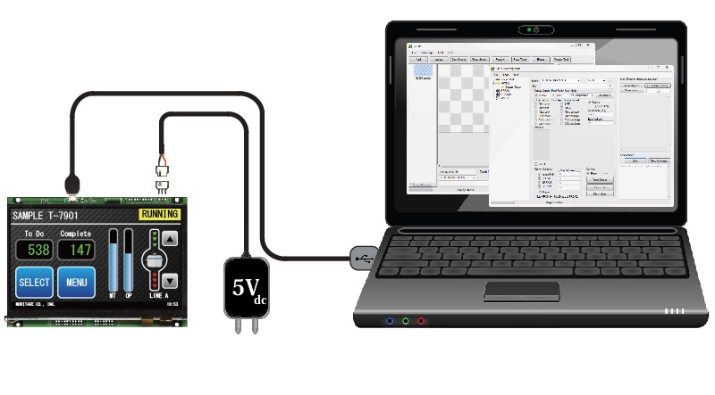
GTOMP provides a quick and easy way to evaluate our GT-CP module. This application allows you to display images on GT-CP modules, create graphical user interface (GUI) prototypes, and download touch setting package data. Choose from either USB or UART to communicate with any of our GT-CP displays.

This tool is a GTOP upgrade and combines our GT-Packer and GTO tools into a single support tool suite. GTOP will not receive any more updates after GTOMP is released.

NOTE: This tool is currently in BETA. Certain features are still in development and testing. Please read the user guide before using this tool.

GU-TFT-Tools-with-PC-image
Download Update: 09-27-2021

System Requirements:

  • Microsoft Windows 10 (32/64-bit) with .NET framework 4.5
  • Serial communication port (USB / UART)
  • 100MB of hard drive space

Application Setup:

  1. Unzip the downloaded file into a folder that you wish to keep GTOMP. It is recommended to keep it in a new folder to avoid confusion with your existing files. You should now have the GTOMP execution file, WinUSB installer for Windows 7 and GTOMP user guide.
  2. The USB communication driver needs to be installed next. If you are using Windows 8.1/10, please skip forward to step 3. If you are using Window 7, please continue to the next step.
    1. Unzip WinUSBdriverForWin7.zip.
    2. Connect your GT-CP module to your PC via USB.
    3. If you have not installed WinUSB or a Noritake virtual COM port driver before, the driver installation will fail. When it does, go to your PC’s Device Manager.
    4. Right click on “GT800X480A-C903PA”, “GTWV050C3A00PA” or “GT480X272A-C903PA” and choose “Update Driver Software”.
    5. Click on “Browse my computer for driver software”.
    6. Click “Browse” and navigate to WinUSBdriverForWin7/winusbcompat.
    7. Click on “Next”.
    8. The driver should install and finish by saying that the “WinUSB Device” driver has been installed.

    * WinUSB is already packaged with Windows 8.1/10 so only install it on Windows 7.

    * If you don’t want to use WinUSB or if you encounter an error during installation, install our GU-TFT driver from this page.

  3. Connect your GT-CP module to your PC via USB.
  4. Launch the GTOMPXXXX.exe file. The main GTOMP window should appear.
  5. You can now use this tool to evaluate your Noritake GT-CP.

Guide:

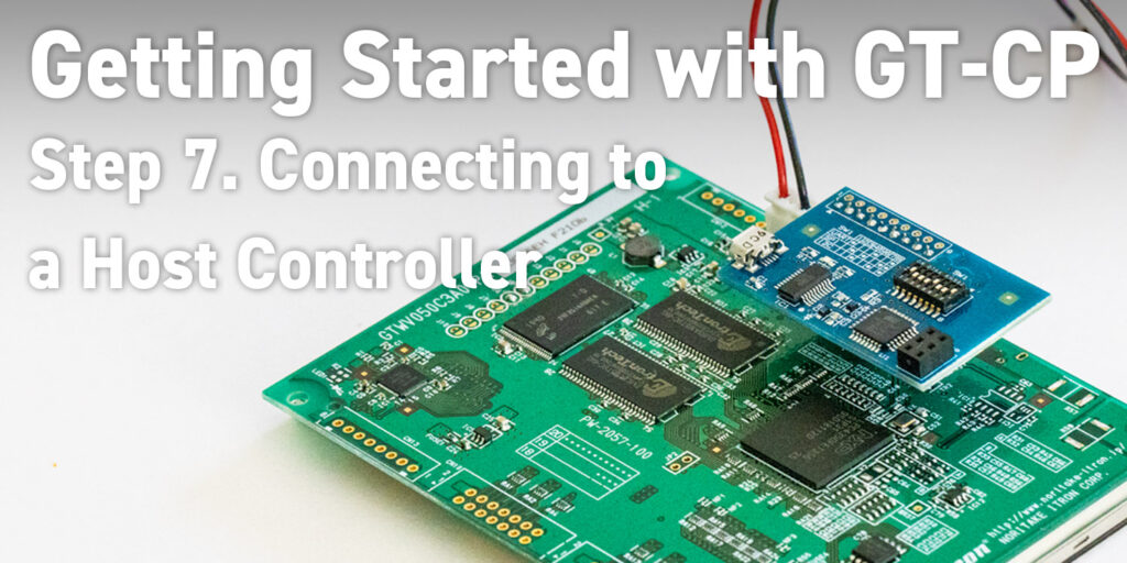
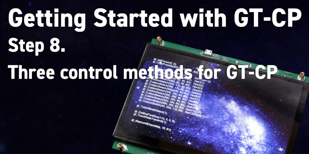
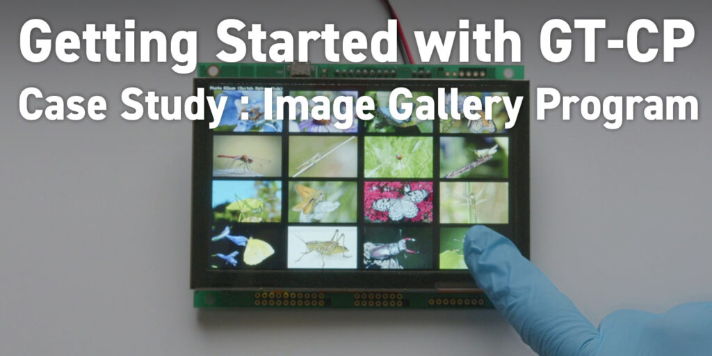
A “Getting Started” guide is available to help guide you through the process of setting GTOMP up with a GT-CP module and using the following basic functions:

  • Print text to the display.
  • Store color image data to display’s FROM.
  • Recall and draw image data to the display from FROM.

Troubleshooting information is also included.

Conditions:

Applicable Display Models:

Tested Operating Systems:

  • Microsoft Windows 10 (32bit/64bit) with .NET framework 4.0 or 4.5

Revision History:

Version Date Revision
1.0.1.5 BETA 01-24-2020
  • Beta version
  • Added touch level tool and package data download tools.
1.1.1.7 BETA 06-10-2020
  • Beta version
  • Numerous bug fixes
  • Added ability for Memory Tool to write to multiple displays at once
  • Other new “work-in-progress” features
1.2.1.9 BETA 10-23-2020
  • Beta version
  • Numerous bug fixes
  • Improved project save/load system
  • Other new “work-in-progress” features
1.2.3.0 BETA 09-27-2021
  • GTOP functionality integration
    • Arduino sketch export to *.ino
  • Added support for new module
    • GTWQ043C3B00PWA
  • Numerous bug fixes

Note:

  • This tool is supplied “As is” without any warranty.
  • Its possible to fail or malfunction under a specific combination of peripherals and PC or operating system.
  • Power requirements are reported as “bus-powered” 100mA. Please check that the USB host/hub is capable of providing sufficient power. When using “bus-powered” mode, please verify the GT-CP module’s power consumption with the module’s hardware specification.
  • This software contains a third party text editor engine called “Azuki” which is developed by Mr. Suguru Yamamoto. For the description of Azuki and its license information are described on https://osdn.net/projects/azuki/

How to check touch sensitivity via monitor tool:

  1. With your GT-CP module connected to your PC and GTOMP open, select the appropriate connection port for the GT-CP module.
  2. Click on “Tool > Touch Level Tool”, the “Touch Level Tool” window will appear.
  3. Touch the connected module’s touch screen. The graph should change accordingly.

Download a touch setting package data file to your GT-CP module:

  1. With your GT-CP module connected to your PC and GTOMP open, select the appropriate connection port for the GT-CP module.
  2. Click on the “Memory Tool” button.
  3. Once the “Memory Tool” window has opened, navigate to “Tool > Touch Setting Package Data > Store > No. 1”.
  4. An open dialog box will pop-up.
  5. Navigate to the desired touch setting package file and click “Open”. The touch package data is now loaded onto the connected GT-CP module as package #1.
  6. Navigate to “Tool > Select a Package > Package 1”. This will select touch package #1 and change the connected GT-CP’s touch setting parameters to match the selected touch package data file.

Display a bitmap image on your GT-CP module:

  1. With your GT-CP module connected to your PC and GTOMP open, select the appropriate connection port for the GT-CP module.
  2. Click the “Memory Tool” button.
  3. Once the “Memory Tool” window has opened, select the serial port that your module is connected to or select “Noritake Display” if you are using WinUSB.
  4. Once the connection is successful, navigate to the image that you would like to display in Windows Explorer.
  5. Drag and drop the image to the FROM2 node located on the left side of the Memory Tool window.
    • NOTE: The recommended image size is 800 x 480 pixels (or 480 x 272 pixels). Image processing time increases as image resolution increases.
  6. A new node will appear underneath the FROM2 node. Click this new node.
  7. The image will then load into the “Preview” section of the application.
  8. Once the image has appeared in the “Preview” section, check the “on GT” checkbox.
  9. The image will now be displayed on the module.

How to Export an Arduino Sketch:

  1. Once your screen design(s) is/are complete, click on the “Export” button.
  2. Choose the location you wish to save the exported Arduino sketch file and name the sketch file.
  3. Once exported, open the Arduino sketch file in the Arduino IDE.
    • The Arduino IDE may move the generated sketch file into its own folder. This is OK.
  4. Upload the generated Arduino sketch to the Arduino host board.
  5. Write the images used in the Arduino sketch to the GT-CP module using GTOMP’s Memory Tool. (if images are used)
    • When the Arduino sketch is exported, an image data binary file “temp.bin” is exported if ROM images are used. Use the “Write Display” button in GTOMP’s Memory Tool to load this image data onto the connected display.
  6. Connect your Arduino host board to the GT-CP module using the wiring reference seen in the Arduino sketch.
    Default Wiring Reference
    GT-CP Display Arduino
    MBUSY A2
    HBUSY A1
    RXD TXD
    TXD RXD
    • Remember to connect power and GND to the GT-CP module and Arduino board.
  7. Add power to the GT-CP module.
  8. Add power to the Arduino host board.
  9. You should see your screen design on the GT-CP module.

Screenshots:

gtomp-screenshot1
Annotation-2019-12-17-085234
gtomp1004_touchleveltool