Series: Getting Started with GT-CP
Getting Started with GT-CP | Step 7. Connecting to a Host Controller
- Connecting to a Host Controller
- Available Serial Interface
- Connection Example: Arduino nano with UART
Series: Getting Started with GT-CP
- Step 1. Connect Display
- Step 2. Install GTOMP
- Step 3. Display “Hello, World!”
- Step 4. Store and Display a Sample Image
- Step 5. Adjust the Touch Sensitivity
- Step 6. Adjust the Touch Sensitivity for Various Cases
- Step 8. Three control methods for GT-CP
- GTOMP Sample Image Menu : Use Sample Program
- Case Study : Image Gallery Program
- Case Study : Tenkey Program
- Case Study : Image Gallery And Slider Program
Connecting to a Host Controller
The GTCP module can be connected to the host controller. This section introduces an example.
Available Serial Interface
GT-CP module has three configurable serial interfaces that are UART, I2C, and SPI. Select one of the three serial interfaces by jumper J5 and J6 on the backside of the module, which can connect to most major microcontrollers. Also, if necessary, flow control is possible by using SBUSY/DTR and TRDY signals. The SBUSY signal reflects the state of receiving buffer. The TRDY signal indicates if there is data currently held in the transmit buffer. To learn more about the GT-CP serial interfaces details, please follow the web links below;
Connection Example: Arduino nano with UART
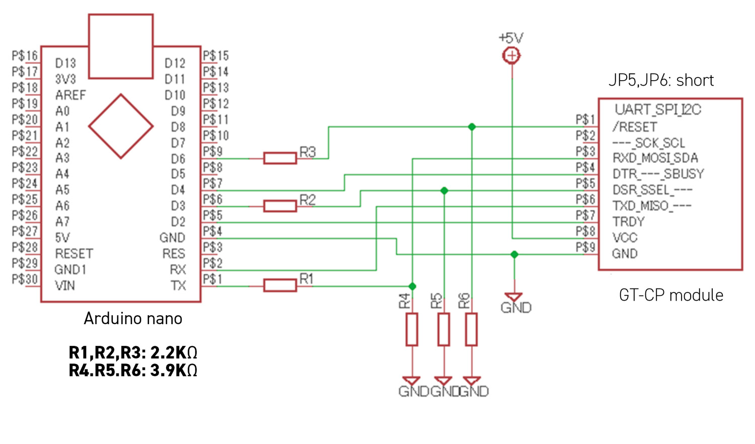
This example is a connection diagram of Arduino nano and GT-CP via UART interface. Setting: JP5, JP6 shorted (UART)

When connecting with a 5V operating microcontroller, the signal level must be changed to 3.3V for the display module. The above example shows how the signal level is changed by using a voltage divider with a resistor. If you want to connect with SPI or RS-232C, see “GT-CP Series Application Note” in the following document list.
https://www.noritake-elec.com/support/design-resources/application-notes
